01The Double Outline Dilemma
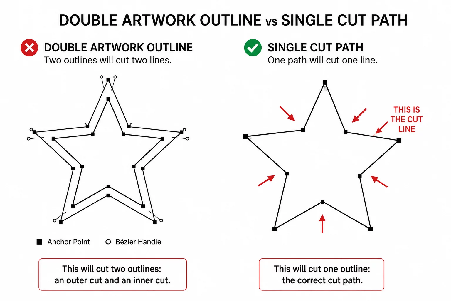
Graphic design software frequently renders line thickness by expanding strokes into closed ribbon-like loops consisting of an inner perimeter and an outer perimeter. While this creates a bold visual stroke on digital displays and color prints, cutting plotters interpret both boundaries as physical knife paths. Consequently, a shape intended to be a single cut out ends up sliced twice, creating paper slivers or destroyed vinyl edges.
Identifying this structure before sending the job to the cutter saves material and prevents cutter jams. In vector wireframe mode, what appeared on screen as a single thick stroke reveals itself as two nested closed vectors separated by the thickness of the stroke itself.
Key Takeaways
- Visual stroke weight in graphic editors converts into dual cutting contours when strokes are outlined or expanded.
- Sending dual parallel paths causes the blade to cut twice along microscopic margins, shredding adhesive vinyl and lightweight paper.
- Release compound paths, identify the primary outer perimeter, and discard the secondary interior trace to retain a clean cut geometry.
02Visual Appearance vs Blade Instructions
Plotters operate entirely without visual perception; they parse mathematical Bézier paths and travel instructions without calculating stroke weights or graphic fills. A four-point black stroke exported without expansion tells the machine to cut along the central centerline path once. However, if the design tool converted that stroke into an expanded outline fill, two independent cut loops now sit side-by-side.
A cutting plotter does not recognize visual thickness. The active cut preview shows which paths have been selected for cutting.
This distinction forms the core rule of vector cutting preparation: artwork is made for the human eye, whereas cut geometry is strict tool navigation. When an artwork file arrives with doubled perimeters, the cutter faithfully slices both, leaving a flimsy ribbon of waste that pulls away and ruins small intricate details.
03Step-by-Step Outer Path Isolation
Resolving this geometry issue requires isolating either the exterior perimeter or the original center axis before initiating the cut process. Follow these systematic vector sanitation steps:
- Switch view mode to Wireframe / Outline mode to expose the exact coordinate tracks the blade will follow.
- Execute Release Compound Path or Ungroup to separate the inner outline loop from the outer envelope.
- Select the redundant inner track and delete it, leaving only the pristine outermost silhouette.
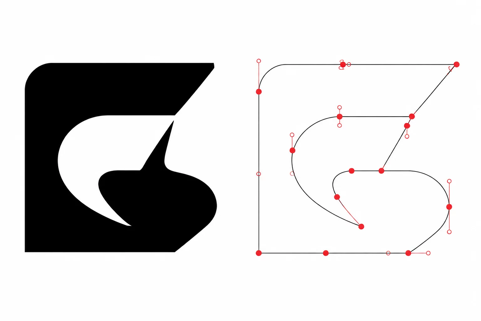
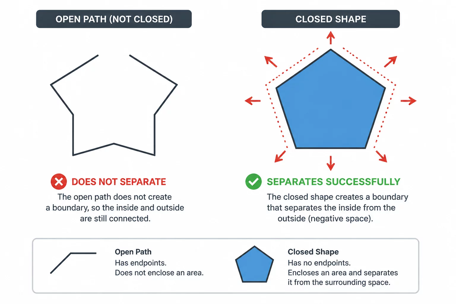
Once the interior parasitic line is cleared, verify the remaining shape by running a path closure audit. Ensure all nodes connect smoothly so the knife enters and exits at the exact same coordinate without stutter.
04Machine Execution & Weeding Results
Performing this simple geometry audit completely alters the physical fabrication outcome. Clean single-loop vectors allow the cutting head to maintain steady downward pressure, glide through corners at higher feed rates, and avoid unnecessary duplicate path travel.
During the weeding stage, the vinyl separates cleanly in one continuous peel without catching on unintended micro-strips. The final cut piece retains its intended structural durability, dimensional accuracy, and crisp borders.