01The Resolution Threshold of Physical Blades
On a high-resolution display, microscopic flourishes, intricate stippling, and hyper-detailed vector filigree appear impeccably sharp. When those exact coordinates are sent to a drag knife or tangential plotter, physical realities take over immediately. A tungsten carbide blade has physical thickness, an offset turning radius, and downward pressure requirements that cannot navigate sub-millimeter turns without shredding the media backing.
When vector coordinates cluster closer than the blade offset angle, the knife rotates continuously in place rather than gliding along a smooth cut line. The result is chewed vinyl, lifted carrier film, and frayed paper stock where delicate flourishes were intended. Recognizing this physical threshold transforms digital illustrations into reliable cut geometry.
Key Takeaways
- Physical blades require clear turning radii, making sub-millimeter curves structurally impossible to cut cleanly.
- Unsimplified autotraces embed hundreds of redundant collinear nodes that force repetitive blade chatter.
- Simplifying vector contours maintains visual character while reducing mechanical wear and weeding failure.
02Identifying Micro-Faceting and Node Clustering
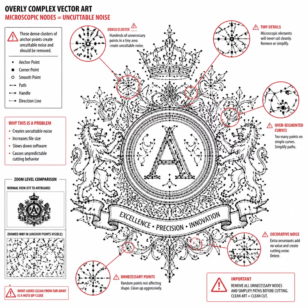
The most common culprit behind uncuttable vector noise originates from automated tracing engines and unexpanded distressed textures. An auto-trace tool converts anti-aliased bitmap gradients into thousands of microscopic polygons. While the shape looks crisp from a distance, node inspection reveals dense serrations along every single contour.
Every anchor point represents a distinct vector deceleration command for the plotter carriage. Over-detailing is not higher fidelity; it is mechanical noise.
When a machine encounters micro-faceting, the cutting head stutters rapidly across microscopic segments. This mechanical vibration degrades cut accuracy across neighboring paths and creates weak adhesive spots that lift during weeding.
03Step-by-Step Geometry Pruning Workflow
Converting decorative noise into workable cutting contours requires deliberate algorithmic and manual pruning. Executing these key adjustments restores clean toolpaths without destroying the overarching artistic silhouette:
- Execute curve fitting algorithms with an error threshold between 0.05 mm and 0.1 mm to merge micro-segments into smooth Bézier arcs.
- Remove internal floating islands smaller than 1.5 mm that cannot withstand standard weeding hook tension.
- Weld overlapping distress marks into unified outer boundaries to eliminate erratic cross-cutting over identical media points.
Applying these structural rules cleanses the vector outline while preserving the expressive silhouette that defines the original artwork.
04Preserving Aesthetic Character Without Chaos
Designers often fear that simplifying vector paths will sterilize the visual energy of organic artwork. In physical manufacturing, the opposite holds true: clean, decisive geometry produces crisp edges, dramatic highlights, and flawless transfer results. Bold, well-defined contours communicate detail far more effectively than jagged micro-cuts that disintegrate upon application.
Always test your cut files in wireframe preview mode at true scale before sending them to the plotter bed. When your vector paths display clean curves with minimal anchor nodes, your physical projects will weed effortlessly and endure with structural integrity.