01Visual Illusion vs Mathematical Vector Paths
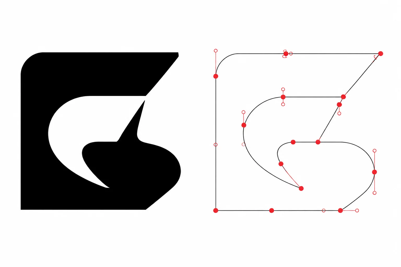
On a digital monitor, design software constructs a visual illusion. Antialiased raster pixels, rich color fills, and decorative stroke weights give the impression of a unified solid graphic. An artist sees a sleek black badge with crisp borders, yet the physical drag knife or laser head perceives none of these aesthetic properties. The machine controller executes instructions strictly along single-dimensional mathematical coordinate trajectories defined by Bézier points and directional handles.
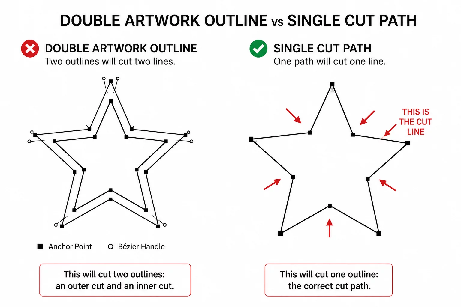
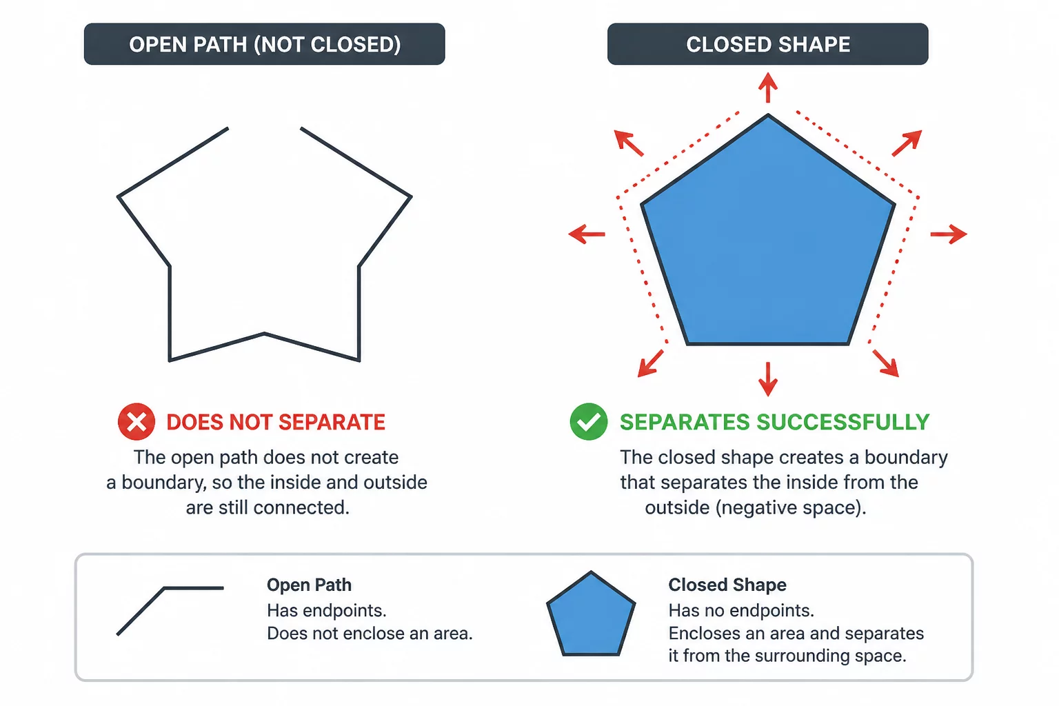
When an artwork file is sent to a plotter without verifying its underlying wireframe geometry, disasters occur. What looked like a seamless unified object on screen may contain three overlapping sub-paths, an open contour, or an unexpanded stroke. The cutting blade follows active cut segments, which can include unintended internal lines if the selection has not been checked.
Key Takeaways
- Plotters follow mathematical centerlines and closed Bézier vectors, ignoring aesthetic fills and stroke thickness styling.
- Visual stacking order in graphics software conceals duplicate overlapping trajectories until sent directly to the blade.
- Switching to wireframe outline mode exposes phantom paths and unmerged intersections before wasting physical vinyl.
02The Trap of Stroke Widths, Fills, and Opacity Masks
Standard illustration software allows creators to apply a 12pt outline to a delicate monogram with a single click. Visually, the letter expands in boldness and weight. Vector cut geometry, however, treats that thick stroke as an infinitely thin line along the center axis of the stroke. Unless the designer intentionally expands that stroke into an enclosed boundary, the cutter blade will slice straight down the middle of the graphic rather than carving around its outer silhouette.
A blade has zero comprehension of visual color or decorative line weights; it strictly obeys coordinate pairs and closed loops.
Opacity masks and white overlapping shapes present an even greater hazard. In graphic design, placing a white circle over a black square creates an apparent cutout. If the rectangle and circle are both active cuts, they can create an outer piece with a circular opening. If the circle is only visual styling, it may create no inner cut. Choose the retained shape, represent the intended boundaries, and inspect the active preview.
03Diagnosing Hidden Overlaps and Phantom Vectors
Before transmitting cut files to Silhouette Studio or any CNC cutting driver, a rigorous geometric audit must take place. Detecting hidden errors requires stripping away visual styling and analyzing the naked path structure:
- Activate wireframe or outline view mode to reveal raw vector coordinates without deceptive fills.
- Inspect path continuity to ensure touching shapes are boolean welded rather than simply layered on top.
- Convert all strokes into outlined paths or single hairline cut-paths depending on the required cut edge.
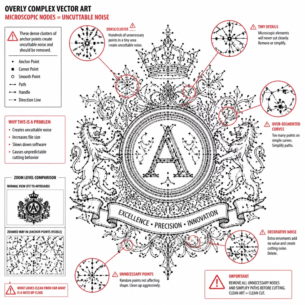
When reviewing vectors in wireframe mode, duplicate identical lines stacked on the same layer become noticeable through darker antialiasing or overlapping node handles. Removing these redundancies eliminates double-cutting, which damages blade tips and tears delicate materials.
04Systematic Remediation Workflow for Clean Cuts
Correcting a visual design into machine-ready geometry follows a disciplined order. Inspect clipping masks and stroke styling, and expand a stroke only when its filled outline is the intended cut shape. Next, apply boolean union operations across overlapping elements of the same color layer to eliminate internal cross-lines. Finally, verify that all internal holes remain connected through proper compound path hierarchy.
Running a simulated cut preview inside your plotting software is the final checkpoint. Red cut lines in the software preview accurately depict every millimeter of blade travel. When the red cut lines match your desired mechanical boundary with zero stray internal loops, the selected geometry is ready for a material test at the intended size.