01The Illusion of Visual Layering vs Knife Trajectory
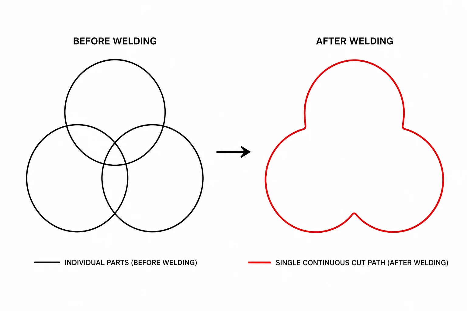
In vector design applications, stacking multiple closed shapes creates the visual appearance of a single composite design. On-screen fills mask underlying strokes, giving an impression of complete solidity.
A cutting plotter or CNC drag knife does not recognize stacking order or opaque color fills. The machine tracks coordinate lines directly. Sending three unmerged shapes instructs the blade to cut every underlying curve, destroying the material structure.
Key Takeaways
- Visual layering masks overlapping vector paths on screen but does not remove them from cut geometry.
- Boolean union operations calculate intersection coordinates and discard trapped interior paths.
- Unmerged overlapping cuts result in shredded substrate pieces and ruined vinyl decals.
02Internal Segment Collision and Material Tearing
Every overlapping path segment creates an unwanted cutting line directly through the core of adjacent shapes. As the knife crosses previously cut vinyl or cardstock, the blade catches on free edges and tears the media.
A cutting plotter does not understand visual depth; the selected paths determine which boundaries will be cut.
Repeated scoring weakens the structural integrity of the sheet and causes small slivers of material to lift into the blade carriage. Merging overlapping boundaries before sending the job eliminates internal blade travel entirely.
03Boolean Union Step-by-Step Geometry Transformation
Merging multiple overlapping shapes into a single clean cut path requires reliable topological reduction. Modern vector engines process this transformation through structured geometric phases:
- Intersection Coordinate Calculation: Finding exact points where path boundaries intersect across shapes.
- Interior Segment Suppression: Removing all path segments that lie inside the composite outer silhouette.
- Boundary Node Welding: Joining exterior segments into a single continuous, closed vector loop.
After the union operation finishes, smooth the junction nodes to maintain continuous tangent curves. This step prevents drag blade hesitation at sharp junction points.
04Verification in Software Cut Preview
Always inspect the design in wireframe mode or the software cut preview tab prior to cutting. In Silhouette Studio or similar applications, active cut lines appear in red and must form a clean single outline with no interior lines.
If internal cut lines remain visible in the preview, release compound paths and reapply the Weld command. A single uninterrupted cut boundary ensures flawless production and effortless weeding.