01The Geometry Behind Compound Paths
When designing multi-layered vector artwork, visual appearances frequently mask critical mathematical distinctions. In standard digital illustration, placing a white circle over a black circle gives the impression of a ring. However, cutting plotters and CNC routers do not read visual surface colors; they interpret raw vector paths as directional trajectories for a physical blade. If both circles are active cuts, the outside and inside contours can form a ring after the center waste is removed. Check the intended retained material and both active boundaries; white fill or path direction alone does not select a cut.
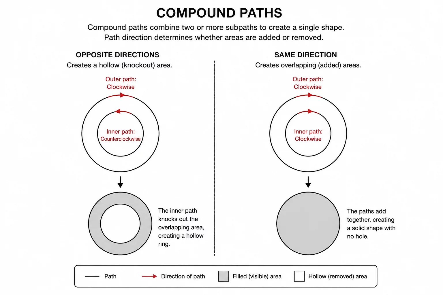
A compound path can represent an opening in filled artwork, while the cut preview must still contain the intended inner and outer boundaries. Inside a compound path structure, the vector software calculates spatial subtraction based on how sub-path vertices sequence from start point to end point. When the inner boundary runs counter-clockwise while the outer contour travels clockwise, the mathematical algorithm subtracts the interior volume. This describes the nonzero fill rule. With the evenodd rule, nesting determines the opening independently of direction. Fill rules describe appearance; verify the inner cut separately. W3C SVG fill-rule reference.
Key Takeaways
- Optical layering does not create physical holes; vectors require true compound path structures.
- Path direction determines whether an interior shape cuts as a cutout or an overlapping island.
- Converting nested strokes into welded compound geometry prevents double-cutting along borders.
02Non-Zero vs Even-Odd Fill Rules in Cutters
Every vector graphics engine utilizes one of two primary filling algorithms: the Non-Zero Winding rule or the Even-Odd rule. The Even-Odd rule determines whether a point lies inside or outside an object simply by drawing a ray from that point to infinity and counting path intersections. An odd count represents interior solid space, while an even count signifies a hole. While Even-Odd logic renders holes effortlessly regardless of path direction in raster preview engines, cutting hardware interpreters often default to the Non-Zero Winding paradigm.
Cutting blades do not parse pixels or visual fills; they execute mathematical vectors whose winding trajectory dictates where material stays and where it separates.
In Non-Zero winding mathematics, path direction is paramount. Rays cast across path segments add plus one for clockwise segments and subtract one for counter-clockwise segments. When an inner path shares the same winding direction as the outer container, the resulting score never drops to zero. Consequently, cutting software may treat the interior counter as solid mass or fail to order the internal cut ahead of the exterior boundary, leading to shredded material or trapped scrap during automated jobs.
03Diagnosing Inverted Hole Defects
When preparing intricate cut files such as stencil typography, mandalas, or geometric emblems, inversion errors frequently manifest during machine setup. Recognizing these defects before launching a job saves expensive media and prevents mechanical blade jams.
- Double-pass perimeters where identical concentric shapes trigger redundant blade passes.
- Inverted cut sequences where the outer contour is severed before internal details are cut.
- Ghost fills in CAD previews where interior cutouts display as solid black shapes.
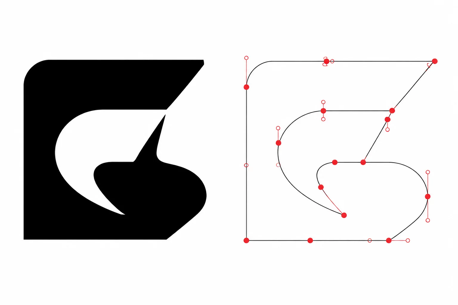
These anomalies almost always trace back to reversed sub-path orientation or broken compound groupings during SVG export. By inspecting the node direction indicators inside node-editing modes, designers can verify that internal cut contours flow counter-directional to outer hulls.
04Practical Corrections in Vector Workflows
Resolving compound path reversal issues involves a systematic vector sanitization routine. First, select the problematic shape and release all compound paths to expose individual sub-paths. Next, select the designated internal cutout path and apply a reverse path direction command. Once reversed, recombine the elements into a single compound path and inspect the resulting cut preview wireframe.
Silhouette Studio and similar cutting software suites provide dedicated tools like "Make Compound Path" and "Subtract All" under the Modify panel. Executing these operations flattens overlapping geometry, normalizes winding directions, and forces the internal counters to cut before the perimeter. Maintaining clean path direction logic ensures flawless weedability and crisp physical edges across every project.