01Defining Enclosed Cavities in Vector Space
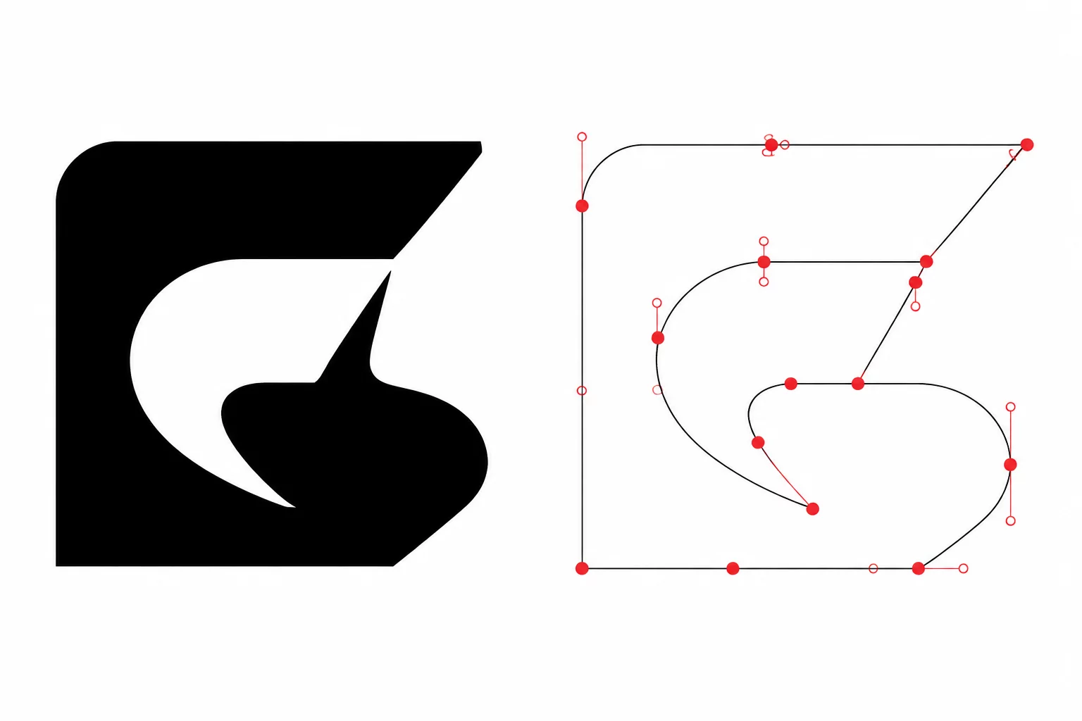
Trapped negative space occurs whenever a vector contour completely encircles an area that must be discarded during physical weeding. Unlike outer silhouettes that separate the entire graphic from waste vinyl, internal cavities exist wholly surrounded by positive material. On screen, these regions often appear as transparent background or white fill, masking their true geometric role.
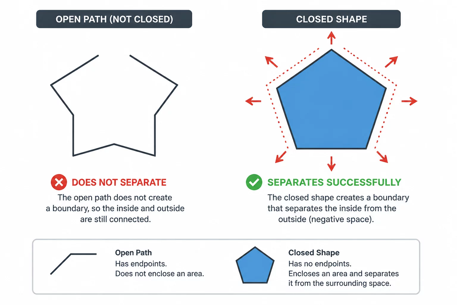
A cutter blade processes geometry strictly by following closed loop coordinates. If an internal loop is absent or improperly grouped as a separate shape, the machine ignores the cavity completely, producing a solid vinyl patch where an open cutout belonged.
Key Takeaways
- Every internal void requires an independent closed vector loop with correct compound path nesting.
- Visual white fills placed over dark shapes fail to generate physical cut lines without vector subtraction.
- Cutting internal cavities prior to outer perimeters prevents vinyl distortion and blade snagging.
02Why Visual Transparency Deceives Cutting Engines
Graphic design applications prioritize visual layering over manufacturing geometry. Designers frequently place white vector shapes over colored backgrounds to mimic negative space. While this trick looks flawless in print or digital rendering, a plotting device does not recognize visual opacity. It reads raw anchor coordinate sequences.
Visual transparency is an optical illusion in vector design. In physical cutting, every boundary is a mechanical knife incision regardless of fill color.
When an unperforated shape carries a white overlay, the plotter knife cuts both the outer perimeter and the internal patch independently. The result is two disconnected pieces rather than a unified silhouette with a true hollow aperture.
03Practical Detection Workflow for Hidden Pockets
To systematically isolate trapped negative spaces before sending paths to the plotter, inspect your artwork through a structured verification sequence:
- Switch your canvas to wireframe outline mode to reveal overlapping white patches masquerading as holes.
- Execute a compound path make command (Ctrl+8 / Cmd+8) to confirm whether interior holes punch through the primary silhouette.
- Verify that tiny cavities have sufficient physical clearance for the blade tip radius and weeding tweezers.
Conducting this inspection eliminates microscopic uncut islands that tear delicate carrier sheets during high-speed plotting jobs.
04Weeding Order Strategy for Enclosed Islands
The structural integrity of your material relies on processing internal negative elements before weeding the master boundary. Stripping the surrounding waste vinyl first leaves delicate internal structures unsupported, causing them to shift or peel away prematurely under blade drag.
Always configure the cutting software sequence to pierce internal negative apertures first. With the broader material web held firmly in place by the mat adhesive, weeding hooks can pluck trapped inner islands cleanly without lifting intricate outer borders.