01The Direct Boundary Dilemma
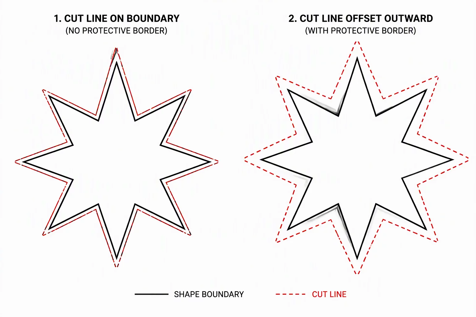
Graphic designers frequently assume that the edge of an illustration serves as its natural cutting line. In print-and-cut or multi-layered vinyl operations, slicing directly along the visible vector border introduces microscopic registration errors. Even a slight mechanical deviation in plotter tracking leaves exposed white halos or slices directly through decorative contour strokes.
An offset boundary creates a dedicated, simplified perimeter surrounding the visual artwork. Instead of forcing the blade to follow intricate decorative indents, a calculated outward expansion isolates the graphic within a solid protective buffer. The buffer changes the finished border. Compare that result with the original boundary and test whether the offset preserves the intended details.
Key Takeaways
- Direct perimeter cuts risk misregistration, white underbase exposure, and premature material lifting.
- Outer offset contours smooth out microscopic artwork noise and reduce total cut time by up to 40%.
- Minimum offset distance should exceed blade kerf diameter and machine mechanical tolerance margins.
02Physical Friction and Blade Drag Dynamics
Swivel blades in craft and commercial plotters do not rotate instantly on a single mathematical point; they trail slightly behind the toolholder center point. When a blade encounters intricate concave corners along an original artwork boundary, the drag friction forces the blade to pivot through tight angles. This physical resistance frequently leads to lifted corners, chewed vinyl edges, or torn adhesive backings.
A cut path is not a visual stroke; it is a physical trajectory of mechanical blade resistance across layered material.
Generating an offset path merges adjacent sharp inner crevices into continuous convex arcs. The resulting path geometry reduces sharp directional reversals, allowing the blade to maintain steady downward pressure and continuous forward momentum throughout the entire cut cycle.
03Determining the Optimal Offset Distance
Selecting the correct offset distance depends on substrate thickness, blade offset calibration, and application requirements. A perimeter that sits too close fails to absorb drift, whereas an excessively large offset destroys the silhouette of the design:
- Tight Decal Offset (0.8 mm to 1.5 mm): Ideal for detailed stickers where the surrounding silhouette must stay tightly matched to original graphic contours.
- Structural Backer Offset (2.0 mm to 3.5 mm): Designed for layered HTV, cardstock toppers, or shadow bases requiring robust structural backing.
- Full Bleed Margin (1.5 mm+ with Artwork Bleed): Guarantees zero white slivers by expanding artwork fill beyond the cut contour boundary.
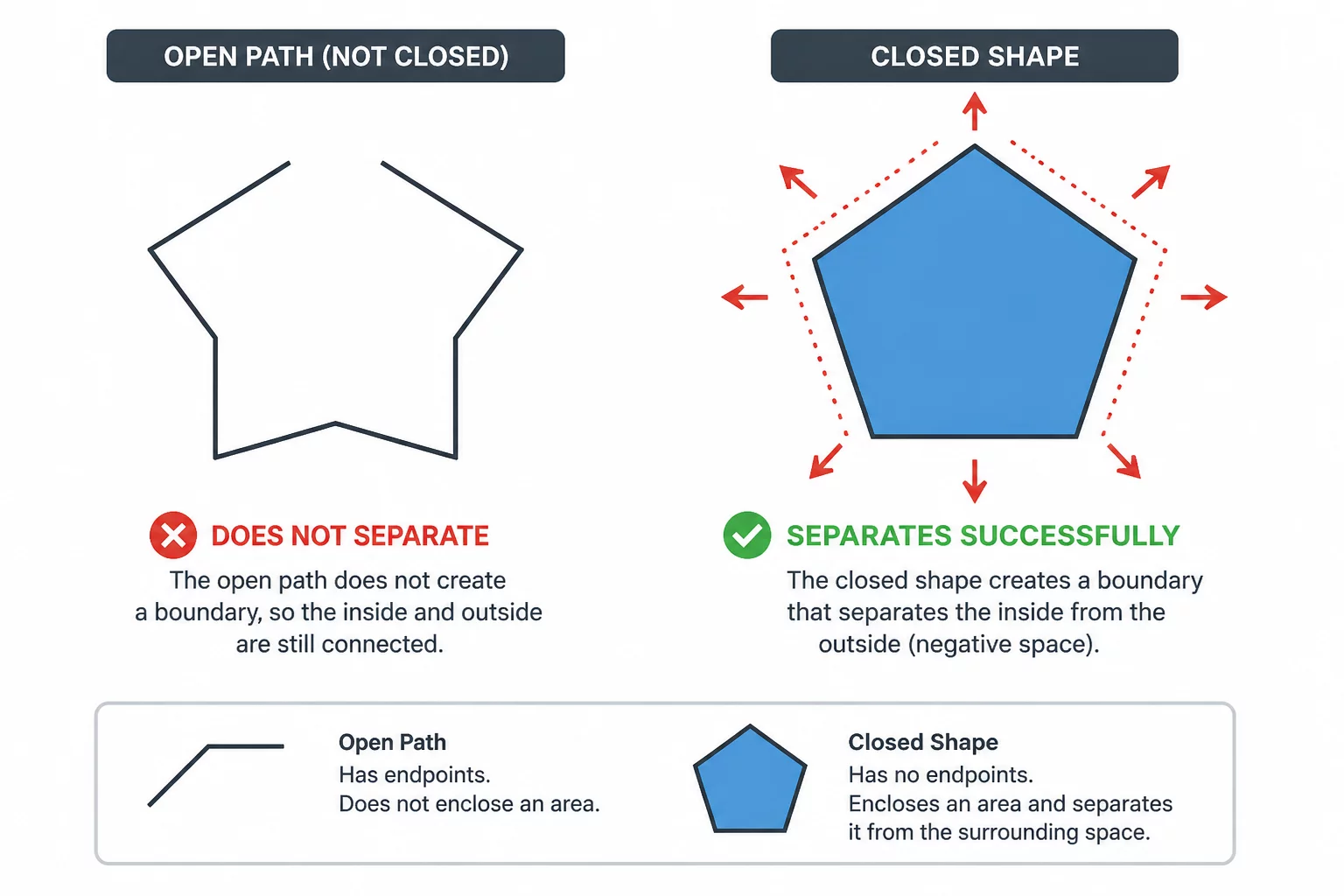
Always inspect internal counter spaces when expanding complex shapes. An outward offset can trap tiny negative voids inside the boundary, which need to be either welded shut or explicitly converted into clean internal weed cuts.
04Workflow Checklist for Clean Offset Creation
Begin by converting all text elements to outlines and merging overlapping vector paths into a single unified compound shape. Apply your software offset tool with rounded corner joins rather than sharp miter corners. Rounded joins eliminate needle-sharp outer vertices that can catch transfer tape and snag during weeding.
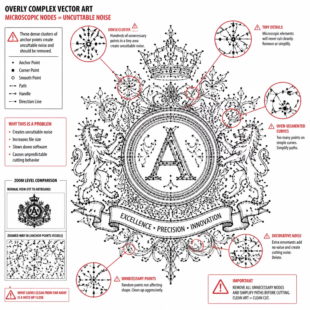
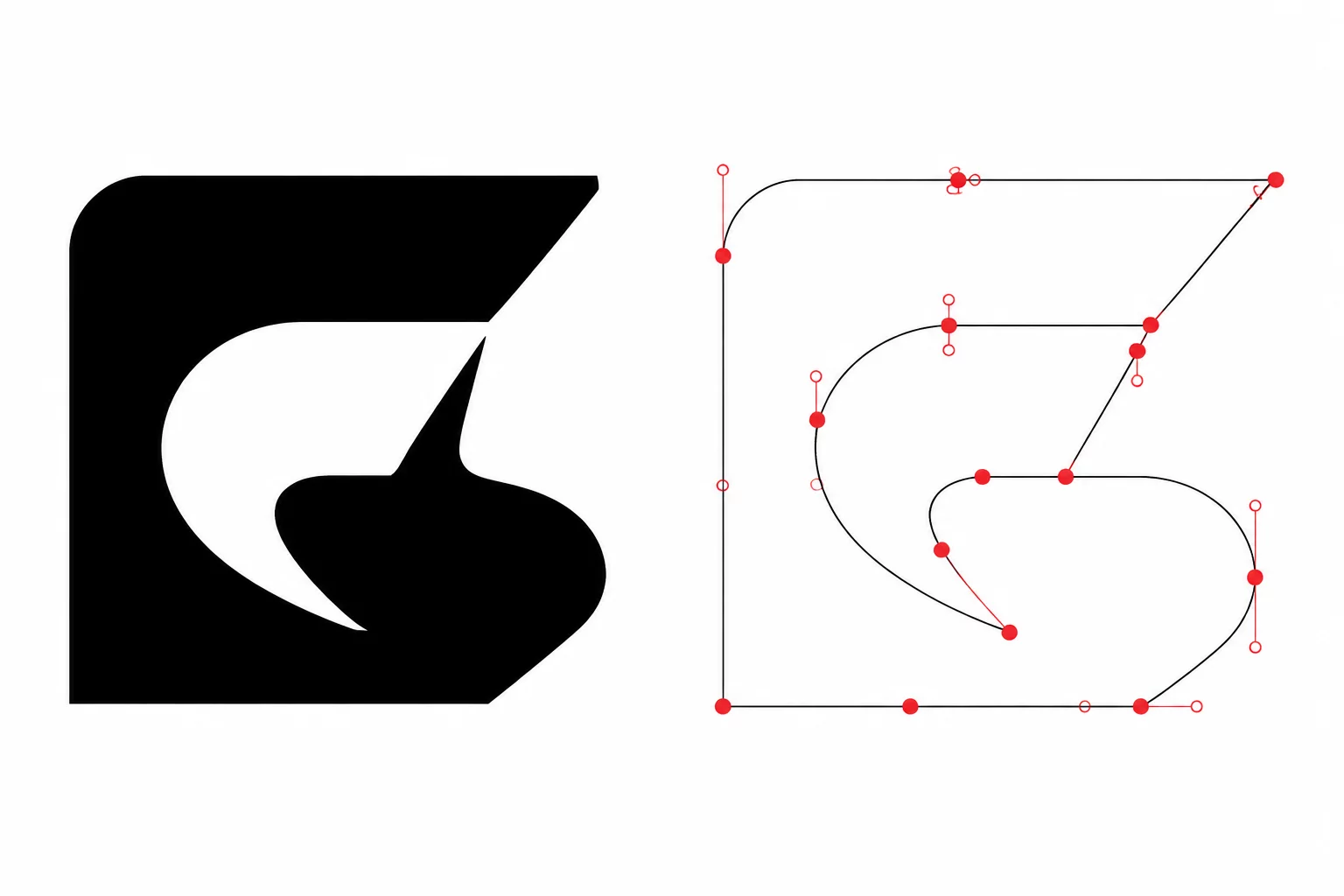
Finally, run a node simplification pass over the generated offset outline. Automated offset algorithms often generate clusters of redundant anchor points along gentle curves. Removing redundant nodes creates a fluid B-spline curve, significantly improving cut speed and reducing motor chatter on desktop cutting machines.