01Offset Expansion vs True Drop Shadow Geometry
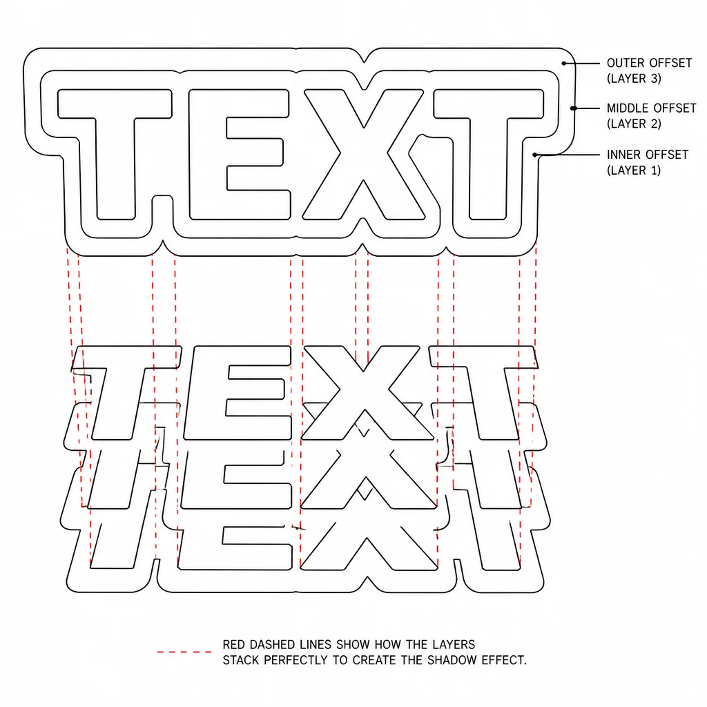
In vector design software, visual drop shadows rely on directional pixel blurs or translated raster duplicates that fade smoothly into background elements. Physical cutting plotters and laser heads cannot interpret transparency gradients, as their motion controllers only recognise discrete coordinates connected by vector paths. Converting a visual shadow into a physical layer requires expanding the artwork perimeter outward symmetrically using offset distance algorithms.
Directional shadow layers require two independent operations: an outward radial expansion followed by an intentional vector shift along the X and Y axes. Attempting to create a shadow layer by simply copying and scaling the original vector distorts line weights unevenly across narrow stems. Calculating a true geometric offset preserves uniform border thickness around complex letterforms and intricate contours.
Key Takeaways
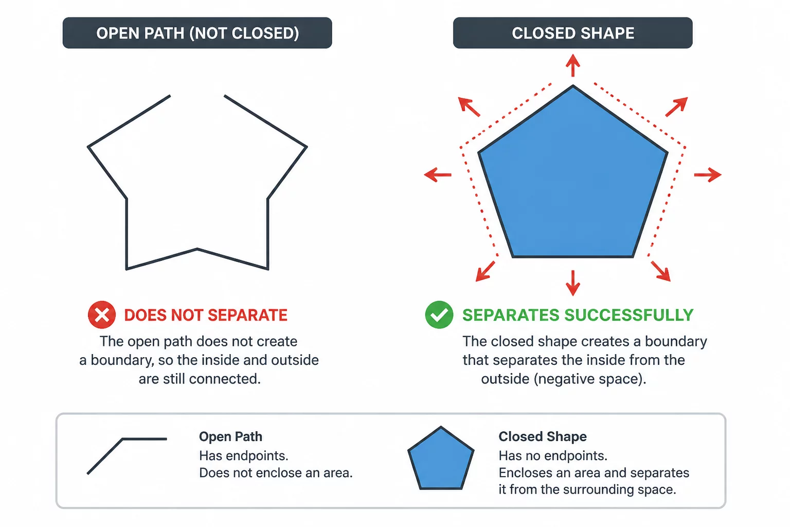
- Physical shadow layers require closed vector boundaries rather than raster blurs or soft gradient transparencies.
- Uniform offsets maintain consistent edge thickness, whereas scaled duplicates distort aspect ratios across narrow stems.
- Small interior gaps must be merged or purged before cutting to prevent torn cardstock and blade snagging.
02Managing Negative Space and Internal Trapped Islands
As an artwork outline expands outward, adjacent letter stems and fine interior loops begin to merge into one another. This geometric expansion often leaves behind microscopic internal voids or trapped negative spaces that measure less than one millimeter across. Leaving these tiny islands in your cut file forces the machine blade to perform sharp micro-cuts that frequently chew through paper fibres or snag adhesive vinyl transfer tape.
An offset contour that preserves pinhole voids creates structural failure points during vinyl weeding and cardstock assembly.
Removing internal counters from background shadow layers simplifies both the cutting path and the physical assembly sequence. For an intentionally solid backing, remove only the holes that should be filled in that layer. If the backing should retain an opening, preserve its inner loop and test it at the intended size. Compare the backing with the foreground before deciding which material should remain.
03Node Consolidation Across Sequential Tiers
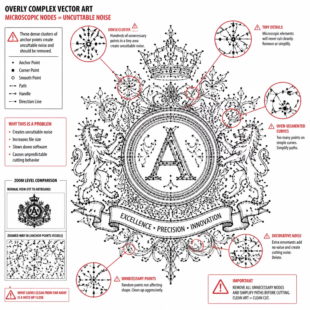
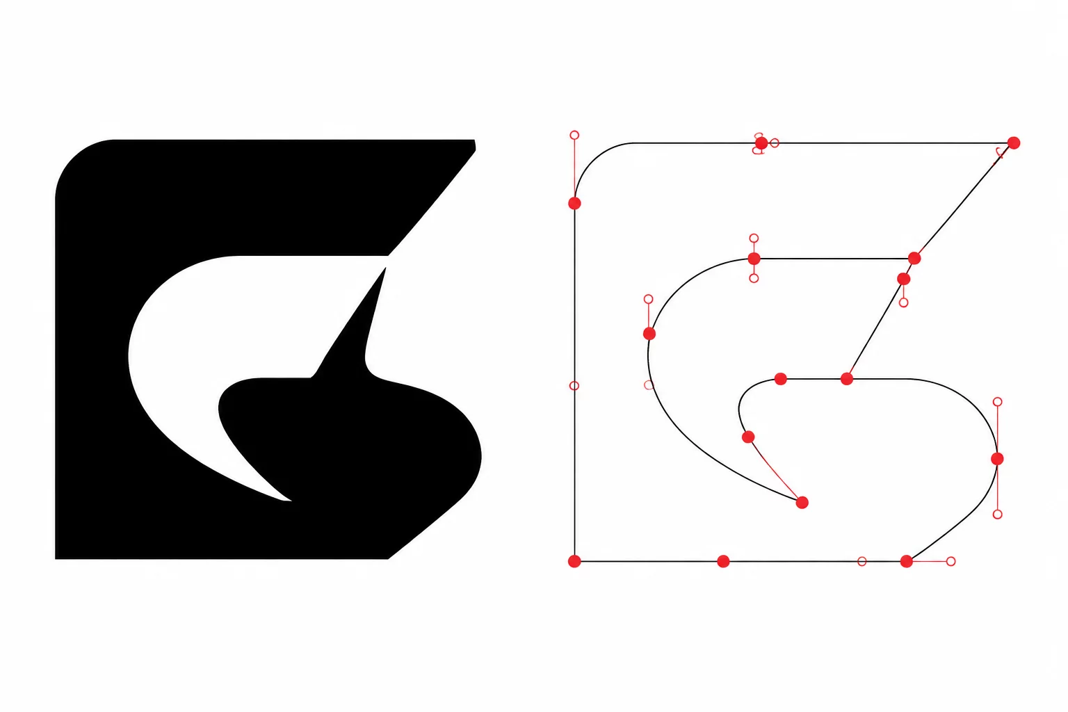
Every successive outward offset calculation introduces supplementary Bézier nodes along outer curves and sharp corners. When stacking three or four concentric shadow layers, node counts can balloon exponentially, resulting in jagged contours and choppy machine movements.
- Apply path simplification algorithms immediately after each offset generation pass to eliminate redundant collinear nodes.
- Convert acute internal corners into subtle fillet radii to avoid violent machine direction reversals.
- Weld intersecting letter groups into unified compound shapes prior to applying tertiary shadow expansions.
Maintaining clean node topology keeps the cutting carriage moving in smooth continuous arcs. This reduces mechanical chatter, prolongs blade lifespan, and produces pristine edge bevels across dense cardstock and thick cast acrylic.
04Material Kerf and Physical Stacking Tolerances
Designing multi-layered dimensional cuts requires accounting for the physical beam width or blade kerf of your cutting hardware. A digital offset of 1.5 millimeters produces a slightly narrower visible border if the cutting tool removes material along the centreline of the path. Measuring your tool kerf ensures that backing borders remain crisp and clearly visible once assembled.
When assembling stacked vinyl decals or multi-layer paper craft, subtle registration drift can expose unsightly slivers of backing material. Increasing the offset border step to a minimum of 2.0 millimeters provides generous alignment tolerance, allowing each layer to register cleanly without requiring microscope-level positioning accuracy.