01Anatomy of the Unintended Twin Vector
When converting raster artwork into vector cutlines or importing illustrations created with stroked line art, trace engines frequently generate two distinct contours around a single visual boundary. The algorithm interprets both the exterior border and the interior boundary of a drawn ink stroke as separate closed paths. While this dual geometry displays identically on screen as a filled line, a vinyl cutter or laser plotter reads each path as an individual physical incision, cutting twice across an ultra-thin sliver of material.
Machine vibration, blade drag, and substrate tearing almost invariably follow when two cuts run fractions of a millimeter apart. Identifying whether an artwork contains a stroke expansion or a nested duplicate ring represents the initial diagnostic hurdle. Switching your workspace to wireframe mode immediately reveals whether your shape is defined by a single clean trajectory or a pair of concentric boundaries destined to shred fine vinyl work.
Key Takeaways
- Autotraced raster strokes naturally generate twin boundaries representing the outer and inner perimeter of the ink line.
- Wireframe display mode is the fastest visual test to detect duplicate cutting paths prior to machine output.
- Releasing compound paths separates nested interior vectors from primary external silhouettes for clean removal.
02Release Compound Path vs Ungrouping
Novice vector editors often attempt to select and delete an unwanted inner line using basic group selection tools, only to discover the entire graphic deletes as a single entity. This occurs because twin outlines are typically bound together into a compound path structure. In vector mathematics, a compound path treats multiple sub-paths as one geometric object to punch transparent holes through filled shapes.
A plotter does not understand visual line weight; it only executes coordinate paths. A visible hairline on screen is two passes on the cutting mat if the outline was drawn with stroke expansion.
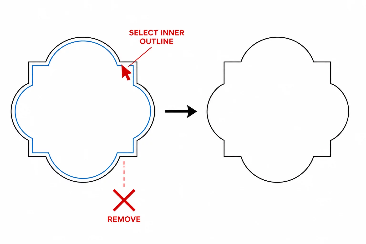
To dismantle this linkage, execute the Release Compound Path command in your design application. This command breaks the parent object into its primitive constituent closed paths. Once released, the outer contour and inner contour become independent vectors, allowing you to select the duplicate inner perimeter and delete it with a single keystroke while preserving the exact exterior silhouette.
03Manual Node Deletion and Boundary Isolation
Certain complex graphics feature intertwined double paths where only portions of the inner boundary repeat. In these tricky scenarios, a simple release command leaves orphaned segments or disjointed corner intersections. Applying a structured isolation procedure prevents unwanted distortion:
- Select the direct selection sub-node tool to isolate the specific anchor points residing along the unwanted interior contour.
- Use path break or knife operations at the shared terminal vertices before deleting intermediate segments to avoid collapsing adjacent curves.
- Join open terminal endpoints on the remaining primary path to ensure the final vector forms an unbroken, airtight loop.
Inspecting the remaining anchor point distribution confirms the elimination of redundant coordinate data. A single unified outline cuts in half the mechanical execution time while eliminating blade drift along narrow channels.
04Machine Path Verification and Kerf Defense
After removing the redundant twin outline, running a send-panel cut preview validates your vector integrity before committing material. The software preview highlights active blade trajectories with colored vector overlays. If any secondary parallel lines still glow in the preview pane, check for unjoined sub-paths or hidden transparent stroke layers lingering in background groups.
Proper double outline elimination preserves exact kerf compensation parameters. When the cutter navigates a single clean path, blade offset calculations remain predictable at sharp corners and gentle sweeps alike. The resulting cut vinyl weeds effortlessly in one continuous pull, devoid of shredded micro-borders.