01Visual Thickness vs Physical Cutting Trajectory
On a digital monitor, setting an illustration line weight to 24 points renders a bold, solid band of color. Graphic designers intuitively expect this bold band to peel off the cutting mat as a thick ribbon of vinyl. However, vector rendering engines and physical plotter controllers interpret paths in fundamentally opposed ways.
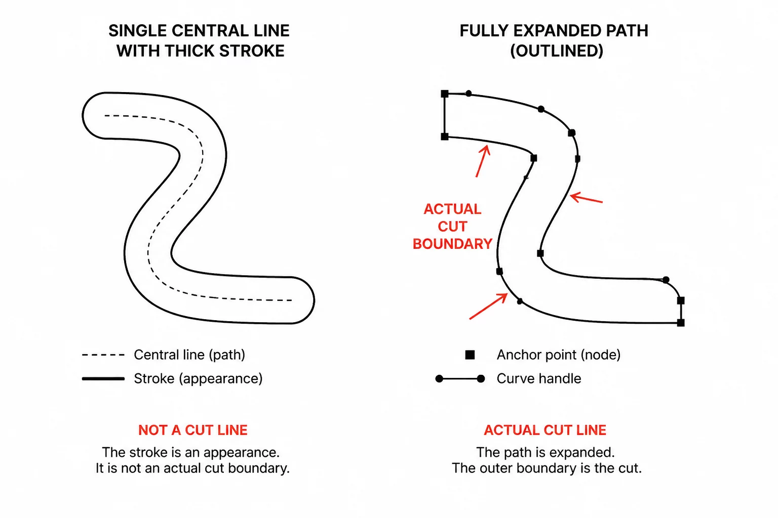
A standard stroke property is merely a cosmetic visual shader drawn symmetrically outward from an invisible 1-dimensional spine. The actual vector path beneath consists of nothing more than two coordinates and a connecting direction vector. When sent directly to a cutting plotter, the blade follows only the mathematical spine, slicing down the exact middle of the design and ignoring the visible ink entirely.
Key Takeaways
- A stroke thickness attribute holds zero geometric surface area in cutter coordinate space.
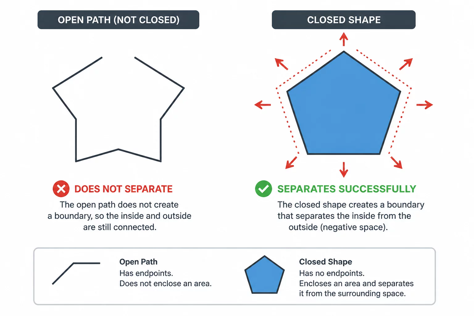
- Converting a stroke to an expanded outline turns one open line into a fully enclosed loop with distinct outer boundaries.
- Failure to expand strokes produces a single material slice rather than a peelable graphic shape.
02What the Cutting Machine Sees: Central Line Coordinates
Hardware drivers communicate with vinyl plotters, laser cutters, and CNC routers using coordinate lists such as HPGL or G-code commands. These commands instruct the carriage motors to move down to coordinate A, lower the tool head, glide straight to coordinate B, and lift up. There is no parameter in basic cutter language for visual stroke weight.
The blade possesses no optical vision. It does not cut what your screen displays; it cuts only what your node coordinates dictate.
When an unexpanded stroke is sent into Silhouette Studio or similar cutting software, the software defaults to tracing the centerline unless explicit outline tools are engaged. The operator watches the blade make a quick single swipe, leaving behind a ruined sheet where the visual width never materialized into a physical peelable border.
03The Expansion Conversion Sequence
To transform a cosmetic stroke into physical geometry, the vector spine must undergo mathematical path expansion (often designated as Outline Stroke, Expand Appearance, or Convert Line to Polygon). This algorithm calculates parallel boundaries equidistant from the centerline and seals the ends:
- Boundary Duplication: The engine offsets the original path positively and negatively by half the stroke width.
- Cap Generation: Open terminal nodes are bridged using flat butts, rounded semicircles, or projecting square caps.
- Spine Discard: The internal central trajectory path is deleted, leaving only the closed outer perimeter.
Once converted, the resulting object features an inner and outer wall enclosing real surface area. The plotter blade now travels around the entire perimeter in a closed loop, liberating the physical shape from the backing carrier sheet seamlessly.
04Resolving Corner Caps and Self-Intersections
Expanding curved or sharp strokes often reveals hidden vector defects that were invisible in standard artwork view. Tight acute corners frequently produce elongated miter spikes, while overlapping line segments create nested internal cut paths that will sever the object into unwanted fragments.
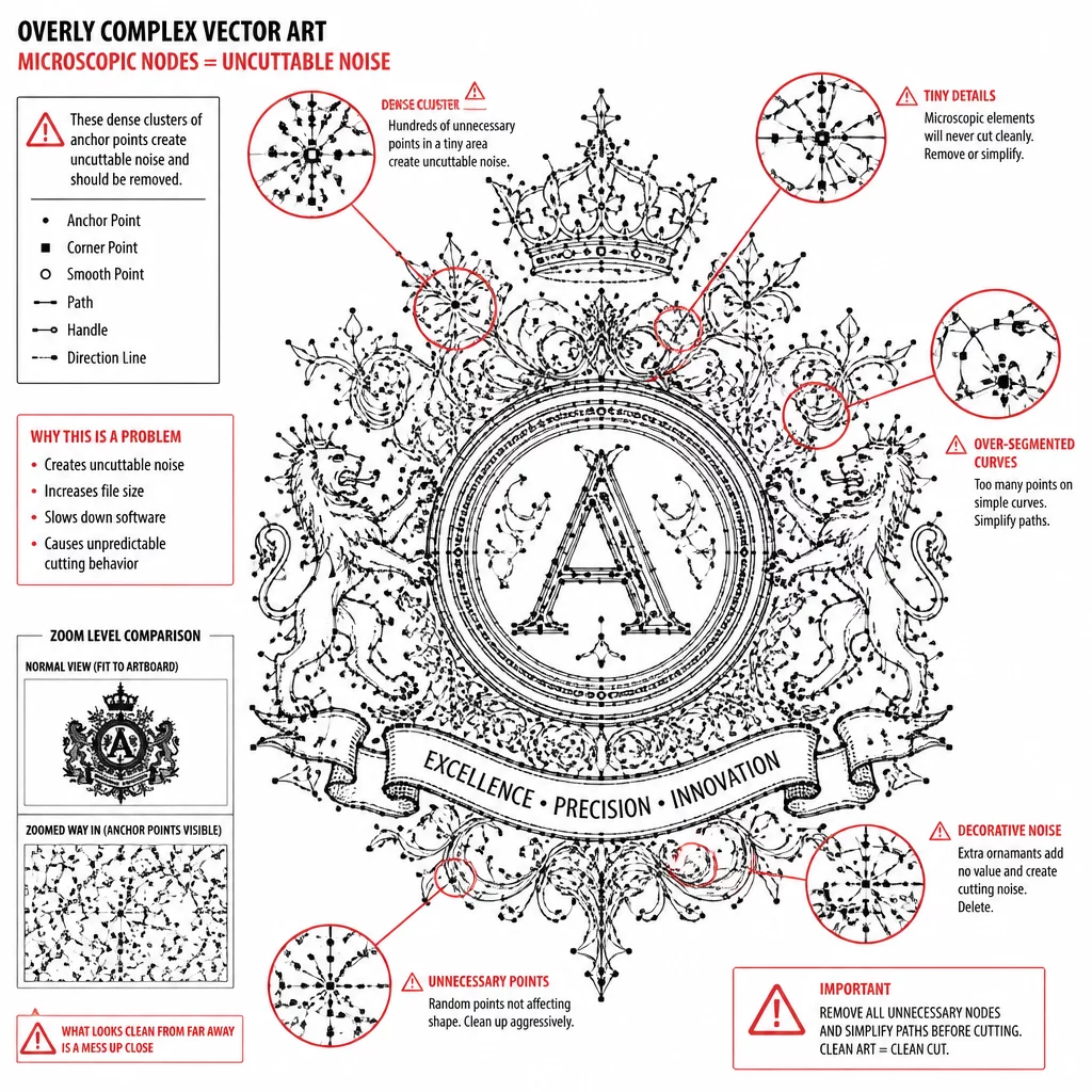
Always inspect expanded graphics in pure wireframe outline mode. Execute a Boolean Union or Weld operation across intersecting strokes to dissolve internal overlap lines before dispatching jobs to your cutting machine. Setting miter limits and round join corners ensures predictable blade turning without tearing delicate vinyl corners.