01The Anatomy of Node Clusters and Blade Chatter
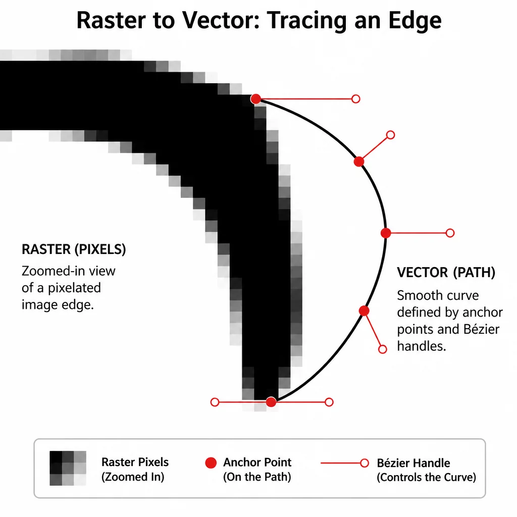
Auto-traced vector artwork and unrefined digitized contours often suffer from micro-fragmentation along supposedly smooth curves. Instead of a flowing cubic Bézier segment, the software creates dozens of tiny linear subdivisions separated by microscopic sharp angle changes. When sent to a physical plotter or drag-knife vinyl cutter, every single node acts as a velocity deceleration command. The tool head stutters, the stepper motors vibrate, and the resulting physical cut features rough serrated edges instead of clean continuous slices.
Identifying jagged node density begins with entering node-edit mode and looking for clusters where three or four anchor points sit within fractions of a millimeter. These dense clusters trap blade rotation, forcing the drag knife to pivot repeatedly in place. This tearing action ruins delicate media like thin heat-transfer film or adhesive vinyl. Understanding how to rebuild these segments with minimal control points guarantees smooth machine movement and extended blade life.
Key Takeaways
- Excessive node density forces plotter motors into micro-stalls that tear delicate media and leave jagged edges.
- Converting cusp nodes to smooth collinear Bézier handles preserves design silhouette while cutting node counts by 70%.
- Simplifying geometry before applying cut offsets prevents compound math artifacts and overlapping loops.
02Bézier Tangent Alignment vs Brute-Force Deletion
The most common mistake vector artists make when cleaning noisy outlines is applying automated global smoothing filters with heavy tolerance sliders. While this reduces the overall anchor count, it frequently collapses delicate inner apexes, shrinks tight radii, and distorts the intended typographic or character proportions. Precision node editing requires targeted deletion paired with intentional Bézier handle alignment.
A flawless cut line is not defined by how many nodes define the shape, but by whether every control handle lies strictly tangent to the path curve.
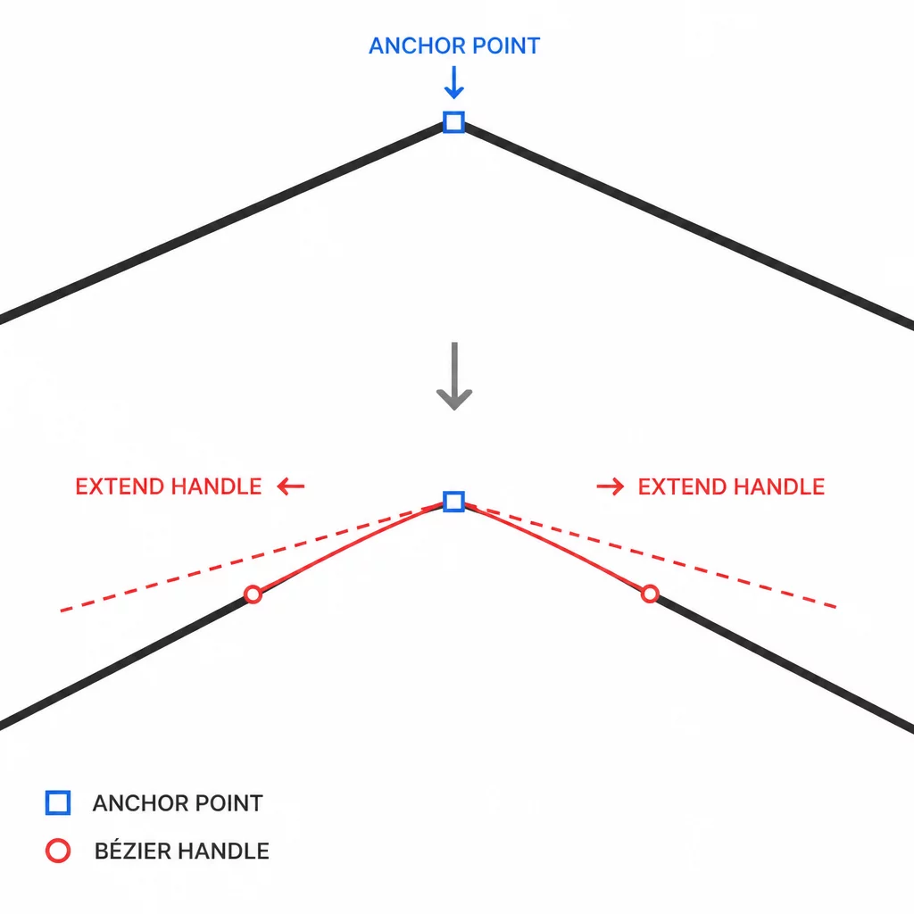
When an unnecessary anchor point is removed, adjacent handle control vectors must be extended and angled to bridge the gap. Keeping handles symmetrical or smoothly aligned along the curvature trajectory ensures that the cutter carriage glides across the transition without registering an artificial corner.
03Step-by-Step Node Decimation Protocol
Executing a systematic cleanup workflow converts problematic auto-traced paths into production-grade cut geometry. Follow this four-stage refinement process before sending files to production:
- Isolate and delete redundant intermediate nodes along shallow arcs, leaving anchor points positioned only at extreme curvature points (inflection points).
- Convert all corner nodes along continuous curves into smooth nodes, extending their Bézier handles until the preview path snaps directly against the original silhouette.
- Inspect tight inner crevices to ensure adjacent handle levers do not cross or form microscopic self-intersecting loops.
Once individual segments are streamlined, test the entire closed perimeter by toggling wireframe outline mode. If the path displays consistent, unbroken curvature without flat facets or irregular bumps, the geometry is ready for machine transmission.
04Machine Velocity and Corner Acceleration Dynamics
Plotter firmware evaluates G-code or cut commands sequentially. A continuous curve constructed with four Bézier nodes allows the cutter controller to maintain constant speed and uniform downward blade pressure. Conversely, a faceted curve composed of forty discrete nodes causes the controller to constantly calculate acceleration and deceleration curves, resulting in uneven kerf depth, partial cuts, and accelerated mechanical wear on the cutter drive belts.
Calibrating your vector curves according to cutting mechanics transforms digital designs into crisp, effortless physical cuts. Investing five minutes in node smoothing saves hours of manual weeding and prevents wasted rolls of high-grade cutting materials.