01The Mechanics of Blade Vibration on Waveform Boundaries
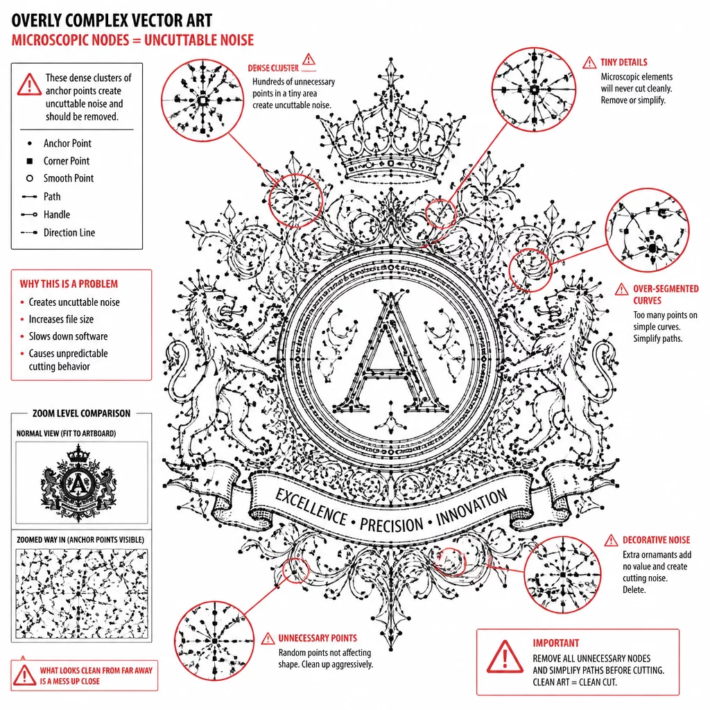
Scalloped borders and repetitive wave patterns frequently cause severe cut failures in plotter hardware. When an edge consists of dense clusters of straight micro-segments rather than clean Bézier curves, the drag knife stutters rapidly across every individual coordinate. The motor attempts micro-adjustments hundreds of times per second, resulting in jagged physical cuts, lifted vinyl corners, and accelerated blade wear.
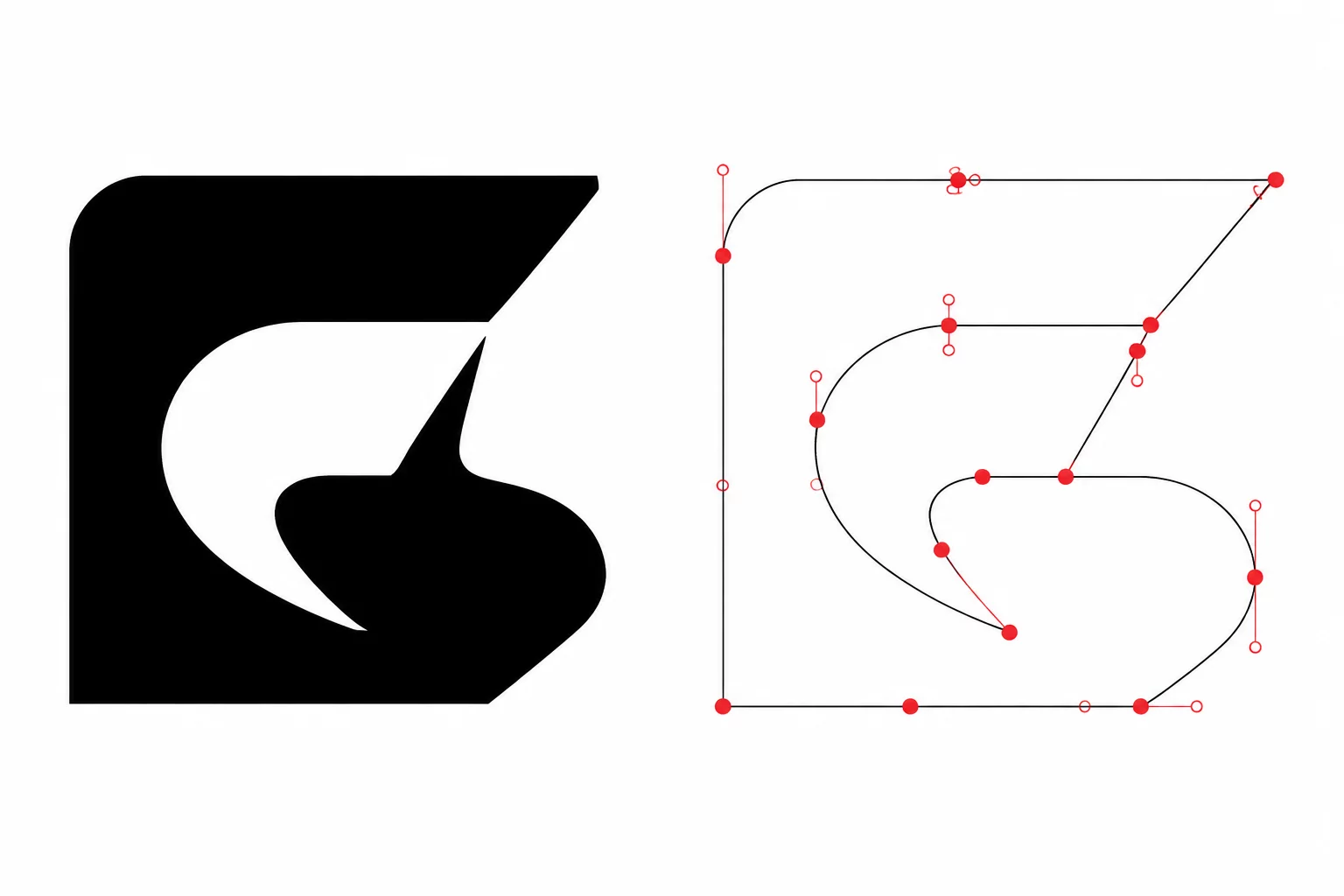
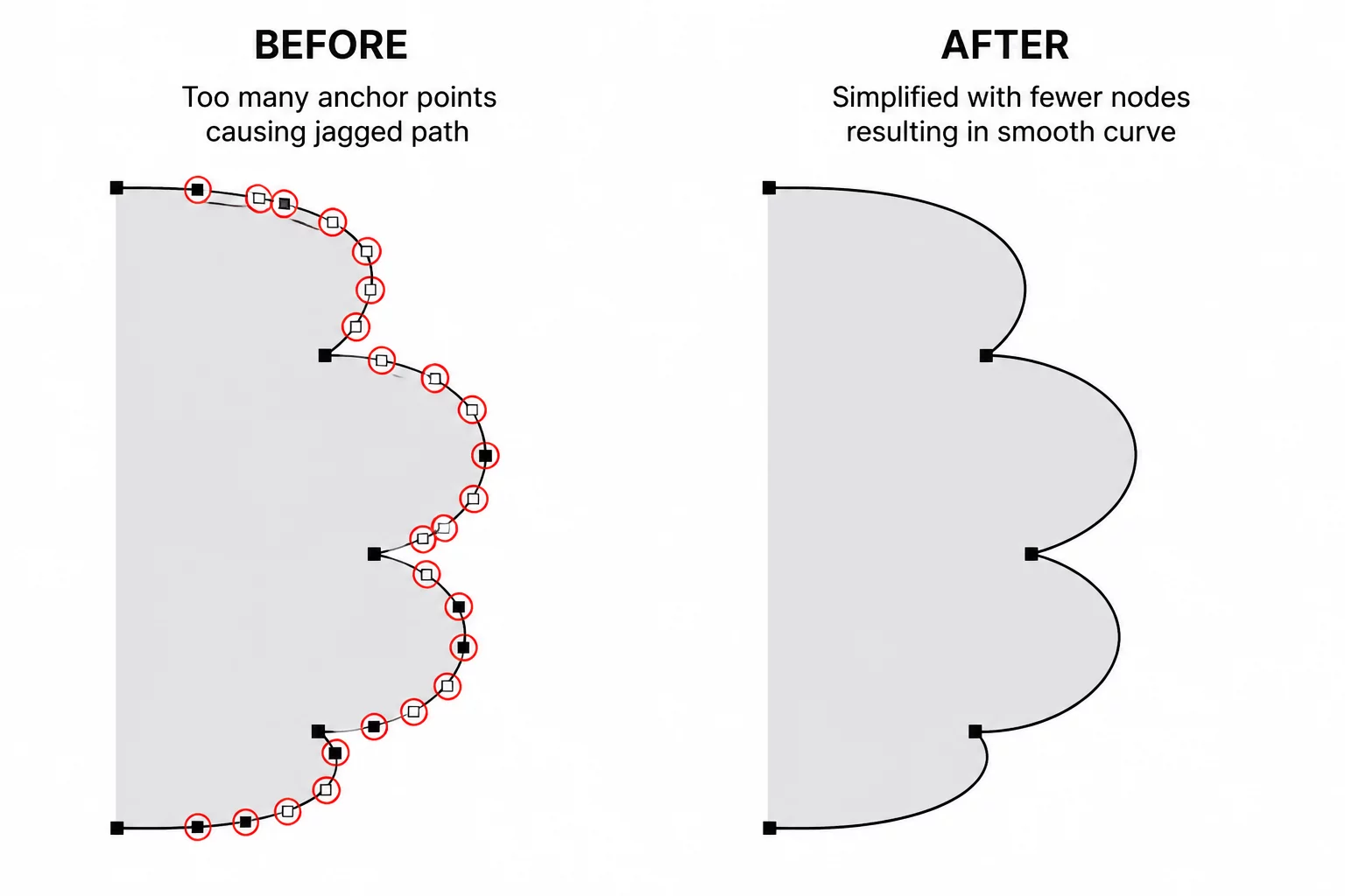
True vector curves rely on tangent handles rather than coordinate mass. By replacing excessive point clouds with balanced apex and valley nodes, plotter speed stabilizes and the blade glides continuously through each curve without stopping.
Key Takeaways
- Excessive point density converts smooth curves into hundreds of jerky linear knife movements.
- Each scallop wave requires exactly two anchor points: one at the crest and one at the trough.
- Symmetric Bézier handles preserve fluid motion while cutting production time by up to 60%.
02Distinguishing Node Bloat from Geometric Geometry
Auto-trace algorithms convert raster scallops into ragged point storms. Instead of recognizing circular segments, tracing tools drop anchor points every few pixels along the edge to mimic anti-aliased bitmap gradients. These redundant vertices introduce micro-angles that the cutting blade interprets as sharp corners.
A cut path does not describe shading or optical smoothness; it is a physical trajectory for a sharp blade under pressure.
Inspecting the wireframe in node edit mode reveals whether a scallop is formed by continuous vector curves or polyline fragments. Removing unneeded intermediate nodes restores mechanical consistency and eliminates tearing at the crest of each curve.
03Systematic Simplification and Arc Reconstruction
Cleaning scalloped vectors requires a disciplined reduction sequence rather than automated global smoothing, which often distorts wave depths. Follow these core geometry principles during cleanup:
- Delete all intermediate anchor points along each scallop arc, leaving only the crest apex and valley junction.
- Convert remaining corner points at valleys to smooth symmetrical anchors or constrained sharp transitions.
- Align Bézier control handles parallel to the base radius to maintain consistent arc height across the entire perimeter.
Applying these structural constraints ensures that every wave matches identical mechanical depth without manual guesswork on individual points.
04Physical Cutting Validation and Weeding Results
Once simplified, the test cut reveals an immediate difference on delicate stock such as adhesive vinyl or heavy cardstock. The blade executes a fluid, silent stroke across the scalloped perimeter without the audible chattering noise associated with unoptimized paths.
Negative space weeds effortlessly in a single continuous pull because the cut line penetrated cleanly through the material without leaving micro-tags or frayed paper fibers at the valley intersections.