01Mathematical Differences in Path Geometry
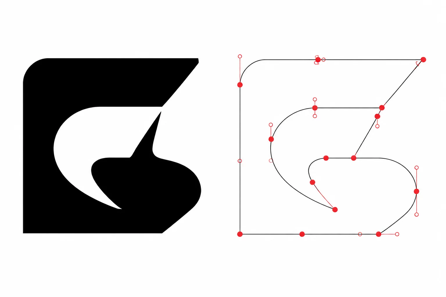
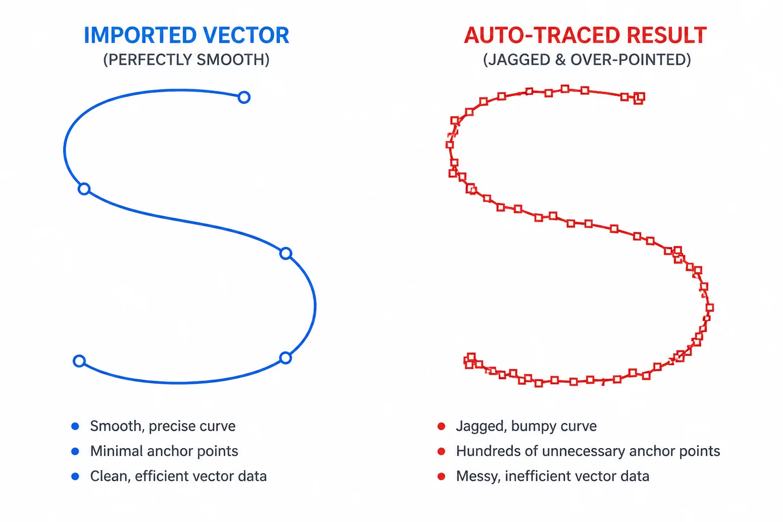
Every digital cutting system interprets boundaries through geometric instructions. Native vector formats, including SVG, DXF, and EPS files, describe shapes through smooth mathematical formulations. A circular arc in a native vector file consists of four anchor points paired with calculated Bézier handles. These handles define continuous curvature without intermediary breaks, giving the cutter carriage smooth directional vectors to follow across the entire trajectory.
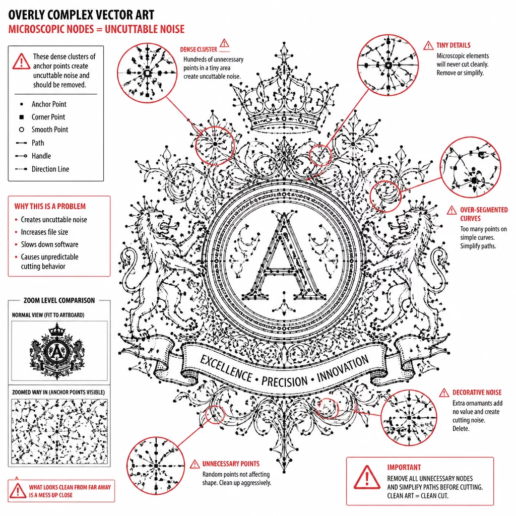
Automated raster tracing algorithms operate under a completely different paradigm. When software processes a PNG or JPEG, it evaluates contrasting pixel transitions through threshold detection. Instead of generating a continuous mathematical arc, the tracing engine constructs a chain of short, linear approximations. A single smooth curve often turns into dozens of closely packed anchor nodes, creating microscopic polygon segments instead of a true parametric curve.
Key Takeaways
- Imported vectors retain true Bézier coordinates that provide smooth carriage motion.
- Auto-tracing converts pixel stepping into hundreds of unnecessary micro-nodes.
- Node density directly correlates with machine shudder, blade chatter, and vinyl tearing.
02The Mechanical Cost of Node Overload
Hardware plotters do not treat excessive nodes as harmless data points. A physical blade holder swivels on a drag-knife bearing as the carriage moves along the X and Y axes. Each time the tool reaches an anchor node with an abrupt angular change, the stepper motors decelerate to adjust trajectory. When dozens of nodes occupy a two-millimeter segment, the carriage experiences continuous micro-stutters rather than smooth travel.
A cutting plotter does not see artwork colors or smooth visual anti-aliasing; it feels every individual node as a physical steering command.
This mechanical stuttering degrades cut quality significantly on delicate media. In thin heat transfer vinyl or cardstock, high-frequency motor pauses lead to localized pressure spikes. The blade pierces too deeply into the backing sheet or pulls fine corners upward during directional reorientation. Weedability drops dramatically as tiny jagged spurs attach the cut shape to the surrounding matrix.
03Workflow Decisions: When to Trace vs Import
Choosing between direct vector import and in-app tracing depends on the source asset quality and intended precision requirements. While direct vector import remains the gold standard, specific production scenarios necessitate tracing. Understanding the boundary conditions helps operators avoid hours of manual node cleanup.
- Import original SVG or DXF files when typography, sharp geometry, and exact tolerances are paramount.
- Use high-contrast threshold tracing only for organic shapes, scanned hand lettering, or hand-drawn sketches.
- Always apply node reduction algorithms immediately after executing an automatic trace operation.
When tracing bitmap graphics, operators must disable automatic high-pass filtering unless capturing fine texture. High-pass filters create duplicate concentric outlines around artwork perimeters. These double contours force the machine to perform dual cuts right next to each other, destroying thin vinyl details and slowing overall run times.
04Optimizing Paths for Crisp Physical Cuts
Converting raw traced paths into production-grade cut files requires structured post-processing. Modern vector toolsets offer path simplification commands that evaluate curvature deviation. Choose simplification tolerance by comparing the original and simplified boundaries at the final size. Preserve intentional corners, openings, and small features; no single tolerance or reduction percentage fits every design.
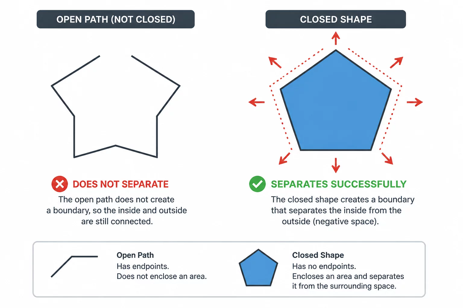
Additionally, check every inner loop for complete geometric closure. Open endpoints cause the blade to lift before completing the cut perimeter, leaving microscopic tabs that tear during manual weeding. Inspecting the wireframe overlay in your software before sending the job ensures clean separation, minimal blade wear, and consistent cutting efficiency across any media.