01The Drag Blade Geometry Dilemma
Plotter cutting blades do not rotate on an infinitely sharp central axis. Standard desktop cutter tools utilize a swivel blade where the sharp cutting tip trails slightly behind the physical rotational center of the blade holder. Because of this mechanical offset, navigating a sharp 90-degree corner without path compensation causes the blade tip to pivot inside the material, dragging sideways through vinyl or bunching up heavy cardstock fibers.
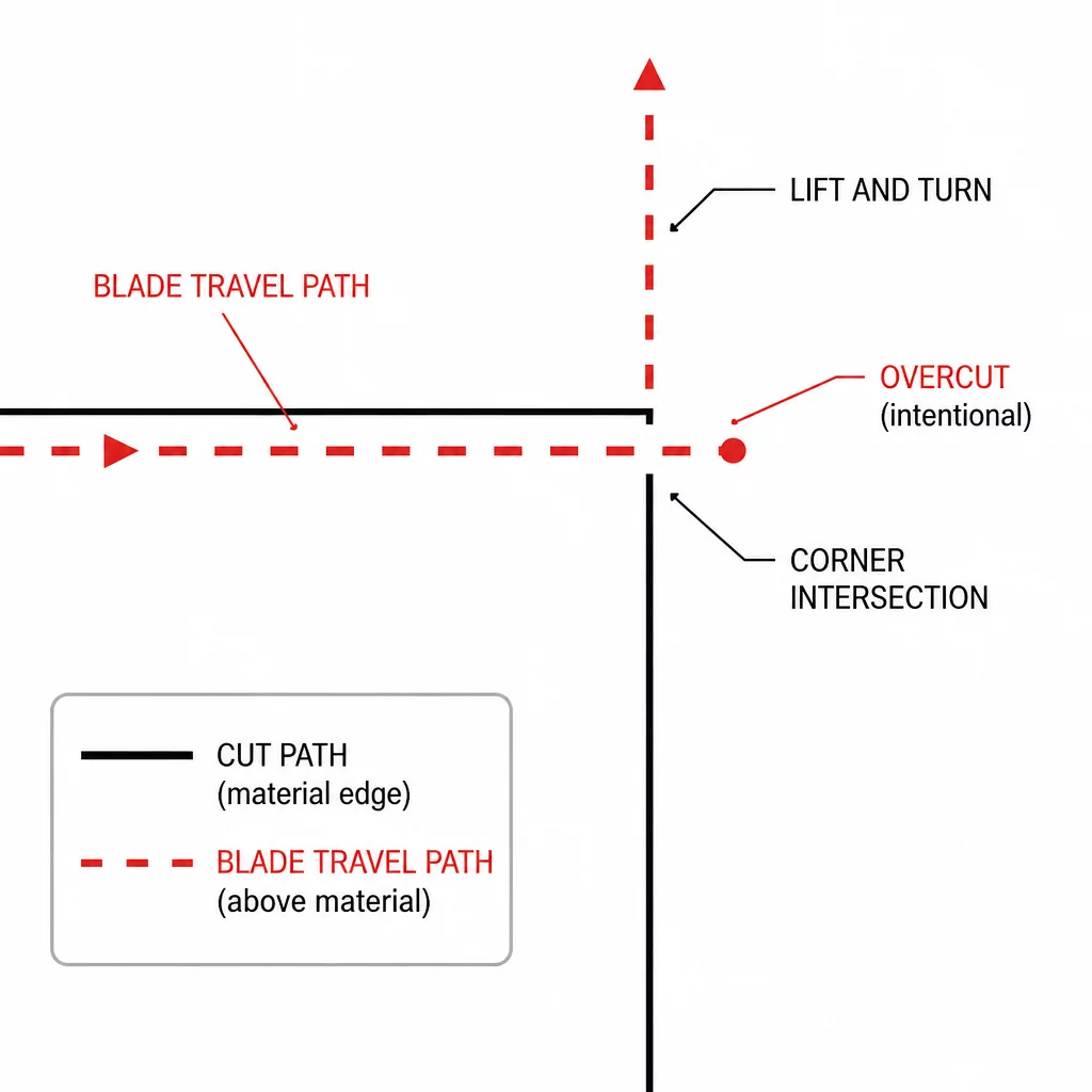
When the tool reaches a sharp vertex and changes direction abruptly, the uncut gap at the corner prevents weeded materials from releasing cleanly. Small triangular vinyl corners lift off the backing sheet or rip entirely during removal. Line segment overcut resolves this exact physical defect by commanding the blade to extend slightly past each corner intersection before lifting, rotating in mid-air, and re-entering the subsequent vector segment from an extended start position.
Key Takeaways
- Drag blades inherently lag behind the tool center, requiring micro-travel beyond coordinate vertices.
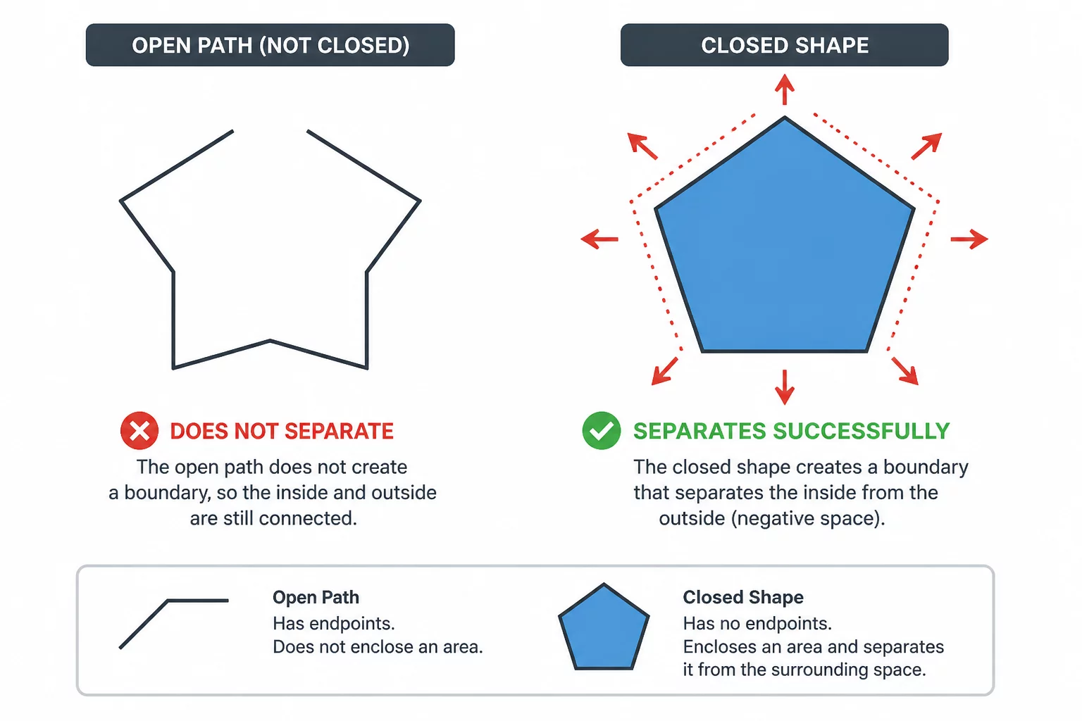
- Enabling Line Segment Overcut splits closed loops into discrete paths with tangential lead-in and lead-out cuts.
- Optimal overcut distances range between 0.1 mm for fine detail vinyl and 0.5 mm for dense cardstock stocks.
02How Segment Overcut Modifies Physical Motion
Silhouette Studio handles overcut by deconstructing continuous vector boundaries into separate directional strokes. Instead of dragging the blade through an aggressive acute turn while pressed down under force, the software creates an artificial overlap. The blade travels past the geometric vertex by a fraction of a millimeter, lifts off the carrier, swivels into the orientation of the next vector stroke, drops down ahead of the node, and cuts backward through the intersection.
An overcut is not an error in vector coordinate generation. It is a calculated kinematic extension designed to compensate for the trailing distance of an offset swivel knife.
This mechanical procedure ensures that both intersecting lines cleanly slice past each other at the corner. As a result, the cut perimeter achieves complete structural separation. When weeding intricate geometric lettering, serif typography, or starburst icons, the residual uncut web disappears, allowing the scrap matrix to pull away smoothly in one piece without snagging delicate tips.
03Configuring Line Segment Start and End Distances
Inside the Silhouette Studio Send panel, activating the Line Segment Overcut toggle exposes specific configuration variables for Start and End extensions. Finding the proper balance depends entirely on media thickness, backing resistance, and design density:
- Adhesive Craft Vinyl (0.1 mm): Minimal extensions prevent excessive overlap marks on glossy face film while providing clean 90-degree corner separation.
- Heat Transfer Film (0.2 mm to 0.3 mm): Thicker polyurethane carriers benefit from deeper lead-outs that sever rubbery film membranes cleanly.
- Heavy Cardstock (0.3 mm to 0.5 mm): High-density cellulose paper requires generous overcut strokes to break resilient fibers that resist single-point swiveling.
Setting overcut values excessively high can cause visible cross-hatch slashes on external borders where lines overshoot the design boundary. Testing small 5 mm corner swatches establishes the ideal minimum threshold for your specific media without creating surface scarring.
04Troubleshooting Torn Material and Rounded Vertices
If your machine continues to tear paper vertices despite overcut being enabled, verify that your blade housing has not accumulated adhesive debris. Vinyl adhesive deposits prevent the blade spindle from freely swiveling in its collar, introducing rotational drag that ruins calculated overcut mechanics. Clean the cap regularly and ensure the blade tip spins freely when turned by hand.
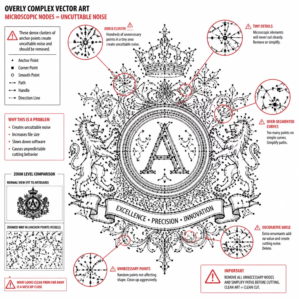
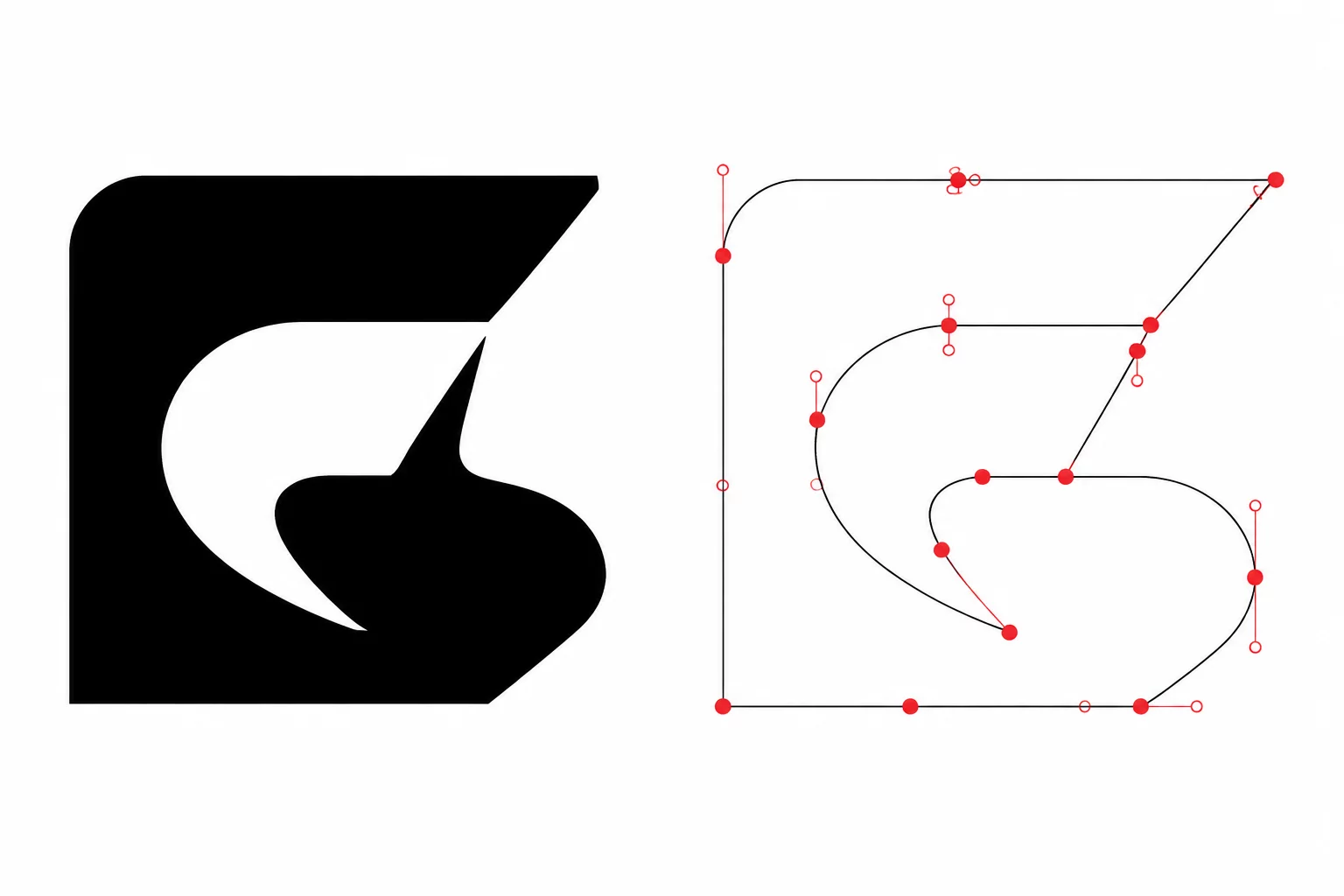
Additionally, check your vector nodes in Silhouette Studio. Complex curves converted from raster traces frequently contain thousands of microscopic clustered points near corner tips. Overcut logic triggers on distinct sharp angle thresholds; redundant micro-nodes cause rapid micro-lifts that chatter across the paper. Run the Simplify Path command to reduce corner points to single crisp vertex nodes before sending the cut job.