01The Critical Gap Between Canvas and Blade Action
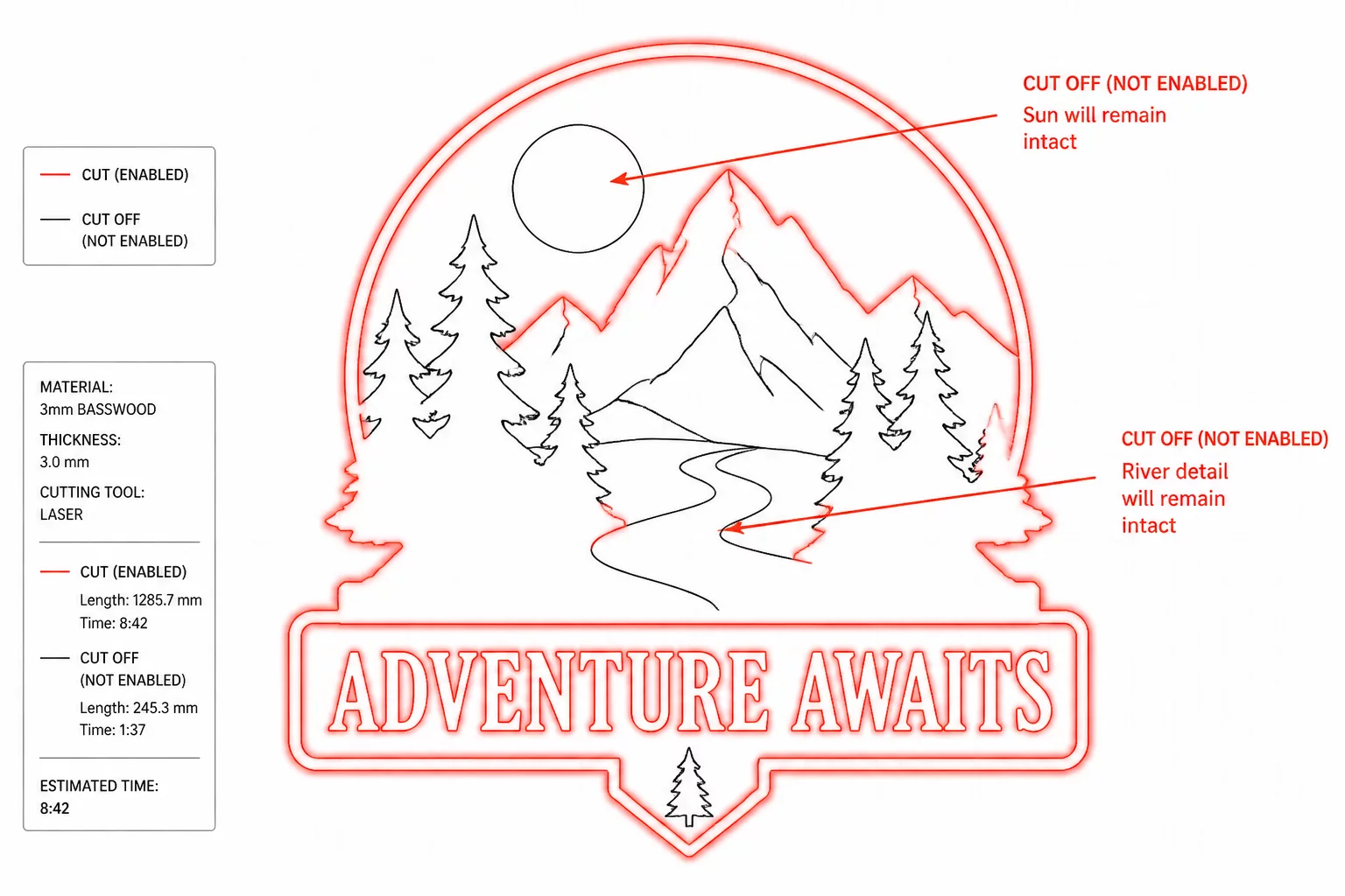
Graphic designers transitioning from digital design to physical plotters often assume that what appears on the canvas automatically defines the blade travel path. On the standard design mat, colored fills, stroke thicknesses, and grouped layers present a finished illustration. When switching to the Send or Action preview panel, the software strips away aesthetic styling and replaces it with a stark vector trajectory map, usually rendered in saturated red lines.
The cut preview overlay represents raw mechanical instructions: coordinates where the tool carrier will lower the blade, engage downforce, and follow vector paths. When an imported SVG contains overlapping elements or cosmetic stroke outlines, the preview overlay exposes every internal slice that would destroy the material if cut uninspected.
Key Takeaways
- Canvas stroke widths are decorative; the blade always cuts down the exact mathematical center of a path.
- Red overlay lines dictate actual physical tool movement, ignoring visual layer stacking and transparency.
- Switching between "Cut" and "Cut Edge" fundamentally alters whether internal loops receive tool paths.
02Interpreting Red Line Action Modes (Cut vs Cut Edge)
Silhouette America documents three Send-panel choices: Cut enables the selected design’s lines, Cut Edge enables its outside lines, and No Cut disables them. Inspect each required inner counter in the resulting preview. Labels may vary with software version. Official cut-line options.
"Never trust visual mat appearance alone. If a path does not light up with the saturated red preview line in the Send panel, the blade carriage will bypass it completely."
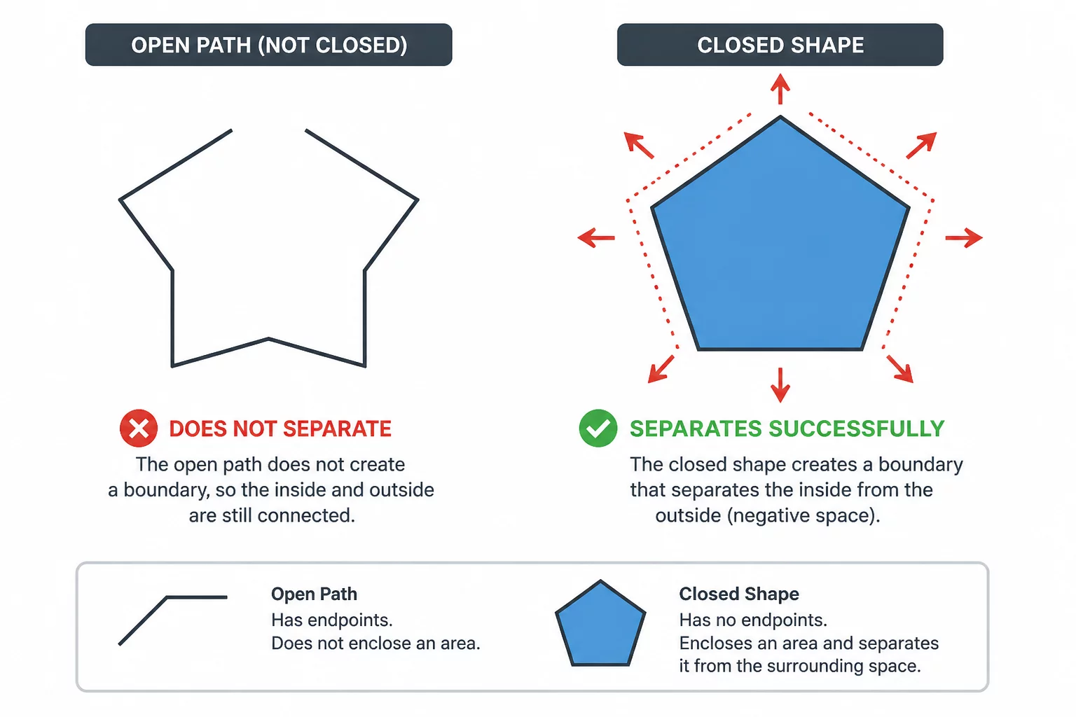
Cut Edge is useful when the intended result is an outside silhouette. Compare its preview with the required holes and internal details. Weld geometry when a permanent combined shape is useful, rather than assuming every overlap must be welded.
03Common Overlay Traps: Hidden Fills and Overlapping Geometry
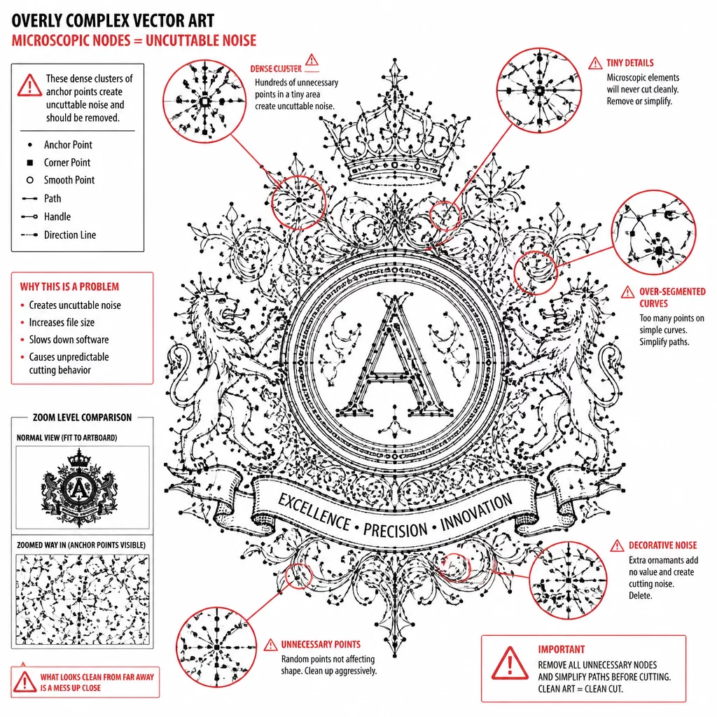
Vector files sourced from illustration programs frequently hide invisible vector paths beneath opaque fills. In standard design view, these hidden paths remain invisible. In the cut preview overlay, they emerge as destructive red cut lines directly across your finished artwork.
- Unwelded overlapping letters create internal slice lines that dice connected cursive words into disjointed fragments.
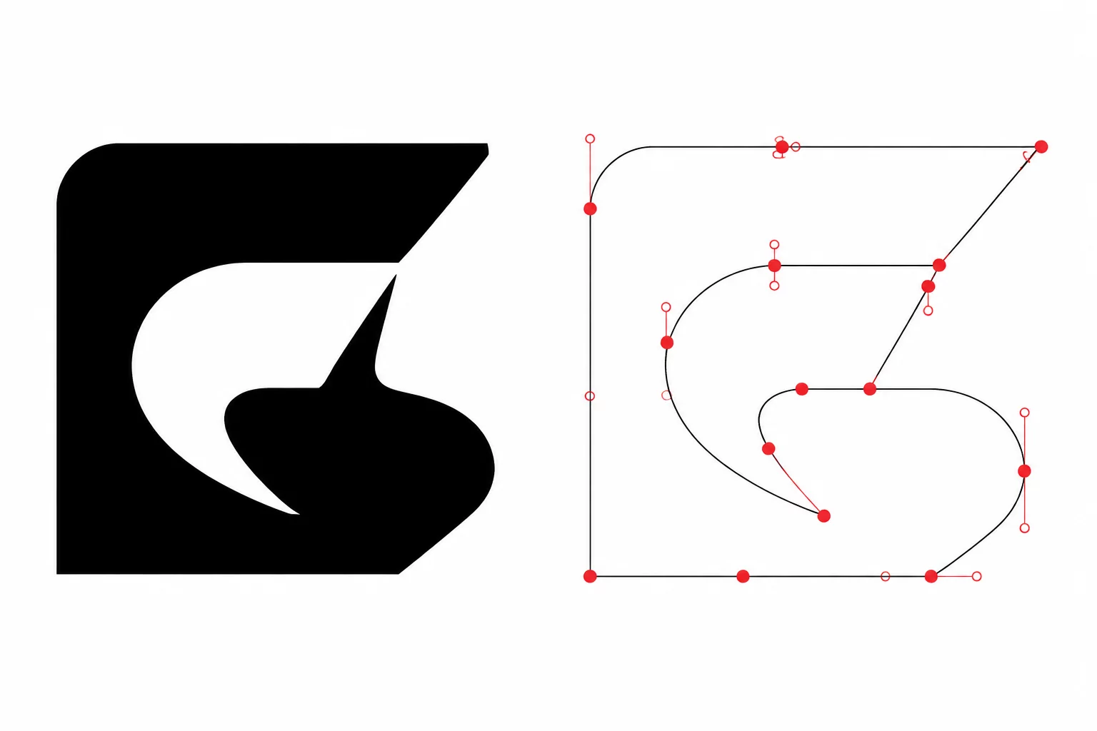
- Stray single-point nodes or zero-length paths trigger micro-blade drops that puncture vinyl without cutting a shape.
- Embedded clipping masks frequently retain invisible bounding box rectangles that generate unwanted full-perimeter cuts.
Inspecting the red overlay at 200% zoom reveals whether internal crossings have been resolved into clean compound paths or remain hazardous collision zones waiting to snag your blade.
04Verification Checklist Before Sending to Plotter
Before pressing the final send command, perform a structured visual sweep across the preview screen. Trace the continuous red contours around delicate elements, verifying that tiny enclosed counters have distinct red loops rather than solid fills. Check that registration marks or alignment guides outside the artwork boundary remain unhighlighted unless intended for pen calibration.
Read the active cut preview alongside the intended finished shape. A material test helps confirm whether the selected outside boundary and inner openings produce the planned result.